M15A-FKS FUEL FUEL PRESSURE SENSOR INSTALLATION
CAUTION / NOTICE / HINT
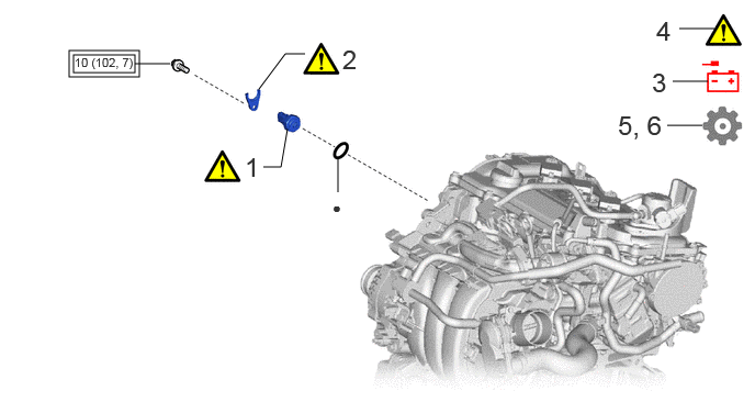
| Procedure | Part Name Code | 
|

|

|
|
|---|---|---|---|---|---|
| 1 | NO. 2 FUEL PRESSURE SENSOR | 89458H | ( ) |
- | - |
| 2 | NO. 2 FUEL PRESSURE SENSOR HOLDER | 23851A | ()
|
- | - |
| 3 | CONNECT CABLE TO NEGATIVE AUXILIARY BATTERY TERMINAL | - | - | - | - |
| 4 | INSPECT FOR FUEL LEAK | - | ()
|
- | - |
| 5 | INITIALIZATION AFTER RECONNECTING BATTERY TERMINAL | - | - | - | ()
|
| 6 | PERFORM INITIALIZATION | - | - | - | ()
|

|
Tightening torque for "Major areas involving basic vehicle performance such as moving/turning/stopping" : N*m (kgf*cm, ft.*lbf) | ● | Non-reusable part |
CAUTION / NOTICE / HINT
- NOTICE:
-
This procedure includes the installation of small-head bolts. Refer to Small-Head Bolts of Basic Repair Hint to identify the small-head bolts.
-
Click hereGeneral>INTRODUCTION>REPAIR INSTRUCTION>PRECAUTION
PROCEDURE

 89458H
1.INSTALL NO. 2 FUEL PRESSURE SENSOR
|
|
|
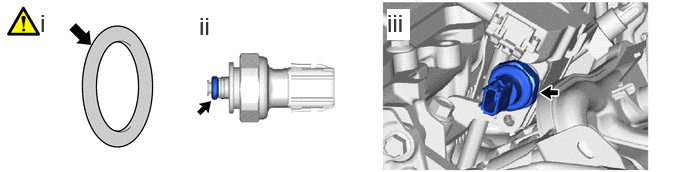
Apply gasoline to a new O-ring.
Install the O-ring to the No. 2 fuel pressure sensor.
Install the No. 2 fuel pressure sensor to the fuel delivery pipe sub-assembly.
23851A
2.INSTALL NO. 2 FUEL PRESSURE SENSOR HOLDER
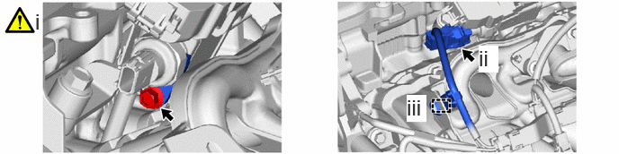
Using an 8 mm socket wrench, install the No. 2 fuel pressure sensor holder to the fuel delivery pipe sub-assembly with the bolt.
- Torque:
- 10 N*m (102 kgf*cm, 7 ft.*lbf)
Engage the clamp.
Connect the No. 2 fuel pressure sensor connector.
3.CONNECT CABLE TO NEGATIVE AUXILIARY BATTERY TERMINAL
4.INSPECT FOR FUEL LEAK
5. INITIALIZATION AFTER RECONNECTING AUXILIARY BATTERY TERMINAL
Click hereGeneral>SETUP>WHEN DISCONNECTING OR RECONNECTING BATTERY TERMINAL>WORK PROCEDURE
- HINT:
-
When disconnecting and reconnecting the battery, there is an automatic learning function that completes learning when the respective system is used.
-
Click hereGeneral>SETUP>WHEN DISCONNECTING OR RECONNECTING BATTERY TERMINAL>AUTOMATIC LEARNING CHART
6.PERFORM INITIALIZATION
Perform "Inspection After Repair" after replacing the No. 2 fuel pressure sensor.
Click hereEngine / Hybrid System>M15A-FKS (ENGINE CONTROL)>SFI SYSTEM>INITIALIZATION