M15A-FKS FUEL FUEL TANK INSTALLATION
CAUTION / NOTICE / HINT
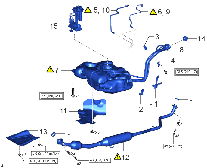
| Procedure | Part Name Code | 
|

|

|
|
|---|---|---|---|---|---|
| 1 | FUEL TANK FILLER PIPE PROTECTOR | 77277R | - | - | - |
| 2 | NO. 3 FUEL TANK FILLER PIPE SUPPORT | 77218A | - | - | - |
| 3 | NO. 1 FUEL TANK FILLER PIPE SUPPORT | 77216A | - | - | - |
| 4 | NO. 2 FUEL TANK FILLER PIPE SUPPORT | 77217C | - | - | - |
| 5 | INSTALL NO. 1 FUEL EMISSION TUBE SUB-ASSEMBLY | 77027B | - | - | - |
| 6 | INSTALL FUEL TANK MAIN TUBE SUB-ASSEMBLY | 77209F | - | - | - |
| 7 | FUEL TANK ASSEMBLY | 77100U | ( ) |
- | - |
| 8 | FUEL TANK FILLER PIPE SUB-ASSEMBLY | - | - | - | - |
| 9 | CONNECT FUEL TANK MAIN TUBE SUB-ASSEMBLY | 77209F | ()
|
- | - |
| 10 | CONNECT NO. 1 FUEL EMISSION TUBE SUB-ASSEMBLY | 77027B | ()
|
- | - |
| 11 | NO. 1 FUEL TANK PROTECTOR SUB-ASSEMBLY | 77606 | - | - | - |
| 12 | FRONT EXHAUST PIPE ASSEMBLY | 17410 | ()
|
- | - |
| 13 | CENTER NO. 4 ENGINE UNDER COVER | 51447D | - | - | - |
| 14 | FUEL TANK CAP ASSEMBLY | 77310A | - | - | - |
| 15 | FUEL SUCTION TUBE WITH PUMP AND GAUGE ASSEMBLY | 77020A | - | - | - |

|
Tightening torque for "Major areas involving basic vehicle performance such as moving/turning/stopping" : N*m (kgf*cm, ft.*lbf) | 
|
N*m (kgf*cm, ft.*lbf): Specified torque |
| ● | Non-reusable part | - | - |
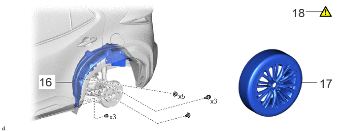
| Procedure | Part Name Code |
|
|
|
|
|---|---|---|---|---|---|
| 16 | REAR WHEEL HOUSE LINER LH | 65638 | - | - | - |
| 17 | WHEEL ASSEMBLY | - | - | - | - |
| 18 | ADD FUEL | - | ()
|
- | - |
PROCEDURE

 77277R
1.INSTALL FUEL TANK FILLER PIPE PROTECTOR
77218A
2.INSTALL NO. 3 FUEL TANK FILLER PIPE SUPPORT
77216A
3.INSTALL NO. 1 FUEL TANK FILLER PIPE SUPPORT
77217C
4.INSTALL NO. 2 FUEL TANK FILLER PIPE SUPPORT
77027B
5.INSTALL NO. 1 FUEL EMISSION TUBE SUB-ASSEMBLY
77209F
6.INSTALL FUEL TANK MAIN TUBE SUB-ASSEMBLY
77100U
7.INSTALL FUEL TANK ASSEMBLY
|
|
|
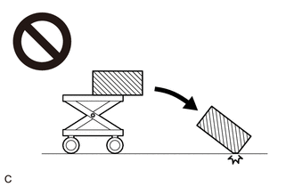
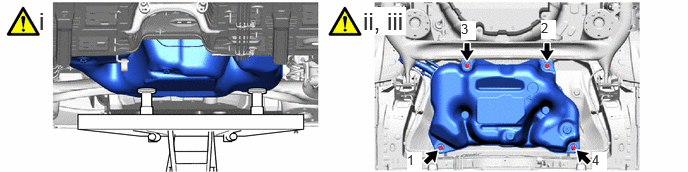
Set the fuel tank assembly on an engine lifter.
- NOTICE:
-
Using height adjustment attachments and plate lift attachments, keep the fuel tank assembly horizontal.
Using the engine lifter, slowly raise the fuel tank assembly, and then temporarily install the fuel tank assembly with the 4 bolts.
Tighten the 4 bolts in the order shown in the illustration.
- Torque:
- 45 N*m (459 kgf*cm, 33 ft.*lbf)
- NOTICE:
- ·
Be careful not to drop the fuel tank assembly.
·When installing the fuel tank assembly, tilt it slightly to prevent it from interfering with the surrounding parts.
8.INSTALL FUEL TANK FILLER PIPE SUB-ASSEMBLY
- Torque:
- 23.5 N*m (240 kgf*cm, 17 ft.*lbf)
77209F
9.CONNECT FUEL TANK MAIN TUBE SUB-ASSEMBLY
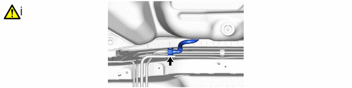
Connect the fuel tank main tube sub-assembly to the fuel pipe.
Click hereEngine / Hybrid System>M15A-FKS (FUEL)>FUEL SYSTEM>PRECAUTION
77027B
10.CONNECT NO. 1 FUEL EMISSION TUBE SUB-ASSEMBLY
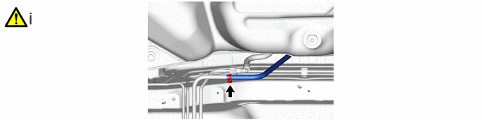
Connect the No. 1 fuel emission tube sub-assembly to the fuel pipe and slide the clip to secure it.
Click hereEngine / Hybrid System>M15A-FKS (FUEL)>FUEL SYSTEM>PRECAUTION
77606
11.INSTALL NO. 1 FUEL TANK PROTECTOR SUB-ASSEMBLY
17410
12.INSTALL FRONT EXHAUST PIPE ASSEMBLY
|
|
Click here()
|
51447D
13.INSTALL CENTER NO. 4 ENGINE UNDER COVER
77310A
14.INSTALL FUEL TANK CAP ASSEMBLY
77020A
15.INSTALL FUEL SUCTION TUBE WITH PUMP AND GAUGE ASSEMBLY
65638
16.INSTALL REAR WHEEL HOUSE LINER LH
17.INSTALL WHEEL ASSEMBLY
18.ADD FUEL