M15A-FXE FUEL FUEL INJECTOR INSTALLATION
CAUTION / NOTICE / HINT
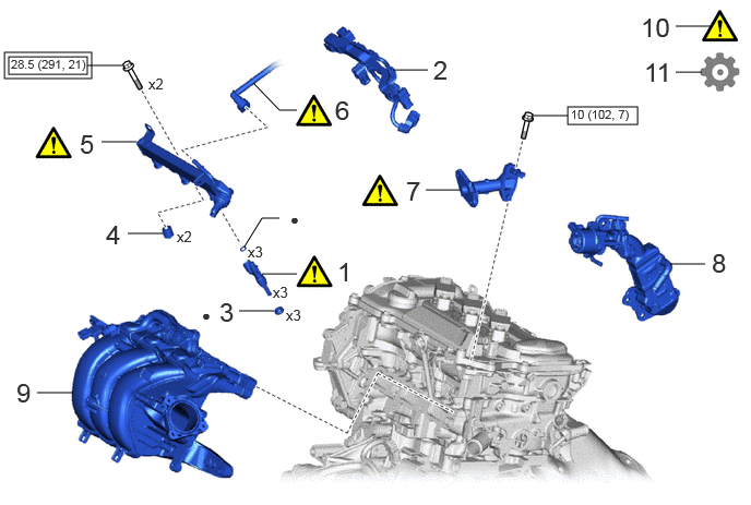
| Procedure | Part Name Code | 
|

|

|
|
|---|---|---|---|---|---|
| 1 | FUEL INJECTOR ASSEMBLY | 23250 | ( ) |
- | - |
| 2 | NO. 5 ENGINE WIRE | 82125N | - | - | - |
| 3 | INJECTOR VIBRATION INSULATOR | 23291 | - | - | - |
| 4 | FUEL DELIVERY SPACER | 23891 | - | - | - |
| 5 | FUEL DELIVERY PIPE | 23814B | ()
|
- | - |
| 6 | FUEL TUBE SUB-ASSEMBLY | 23902 | ()
|
- | - |
| 7 | EGR VALVE ADAPTER | 25624 | ()
|
- | - |
| 8 | EGR VALVE WITH COOLER ASSEMBLY | - | - | - | - |
| 9 | INTAKE MANIFOLD | - | - | - | - |
| 10 | INSPECT FOR FUEL LEAK | - | ()
|
- | - |
| 11 | PERFORM INITIALIZATION | - | - | - | ()
|

|
Tightening torque for "Major areas involving basic vehicle performance such as moving/turning/stopping" : N*m (kgf*cm, ft.*lbf) | 
|
N*m (kgf*cm, ft.*lbf): Specified torque |
| ● | Non-reusable part | - | - |
CAUTION / NOTICE / HINT
- NOTICE:
-
This procedure includes the installation of small-head bolts. Refer to Small-Head Bolts of Basic Repair Hint to identify the small-head bolts.
-
Click hereGeneral>INTRODUCTION>REPAIR INSTRUCTION>PRECAUTION
PROCEDURE

 23250
1.INSTALL FUEL INJECTOR ASSEMBLY
|
|
|
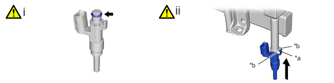
| *a | Stopper | *b | Claw |
Apply a light coat of spindle oil or gasoline to 3 new O-rings, and install one to each fuel injector assembly.
- NOTICE:
-
Check that there is no damage or foreign matter on the groove of the fuel injector assembly when installing the O-ring to each fuel injector assembly.
Install the 3 fuel injector assemblies to the fuel delivery pipe.
- NOTICE:
- ·
Make sure that the fuel injector assembly is located within the stopper as shown in the illustration.
·Check that the fuel injector assembly installation holes of the fuel delivery pipe are not damaged and are free of foreign matter.
·Make sure that the O-ring is not damaged, twisted or moved out of place when installing the fuel injector assembly.
82125N
2.INSTALL NO. 5 ENGINE WIRE
23291
3.INSTALL INJECTOR VIBRATION INSULATOR
23891
4.INSTALL FUEL DELIVERY SPACER
23814B
5.INSTALL FUEL DELIVERY PIPE
|
|
|
- Torque:
- 28.5 N*m (291 kgf*cm, 21 ft.*lbf)
23902
6.CONNECT FUEL TUBE SUB-ASSEMBLY
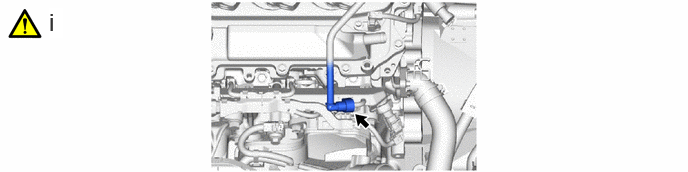
Connect the fuel tube sub-assembly to the fuel delivery pipe.
Click hereEngine / Hybrid System>M15A-FXE (FUEL)>FUEL SYSTEM>PRECAUTION
25624
7.INSTALL EGR VALVE ADAPTER
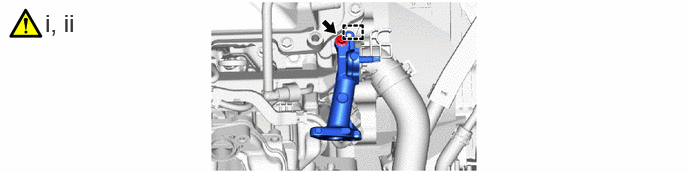
Engage the guide to Install the EGR valve adapter.
Using an 8 mm socket wrench, install the bolt.
- Torque:
- 10 N*m (102 kgf*cm, 7 ft.*lbf)
8.INSTALL EGR VALVE WITH COOLER ASSEMBLY
9.INSTALL INTAKE MANIFOLD
10.INSPECT FOR FUEL LEAK
11.PERFORM INITIALIZATION
Perform "Inspection After Repair" after replacing a fuel injector assembly.
Click hereEngine / Hybrid System>M15A-FXE (ENGINE CONTROL)>SFI SYSTEM>INITIALIZATION