AUDIO / VIDEO AUDIO AND VISUAL SYSTEM Reverse Signal Circuit
DESCRIPTION
The radio and display receiver assembly receives a reverse signal from the park/neutral position switch assembly.
The radio and display receiver assembly receives a reverse signal from the power distribution box assembly.
WIRING DIAGRAM
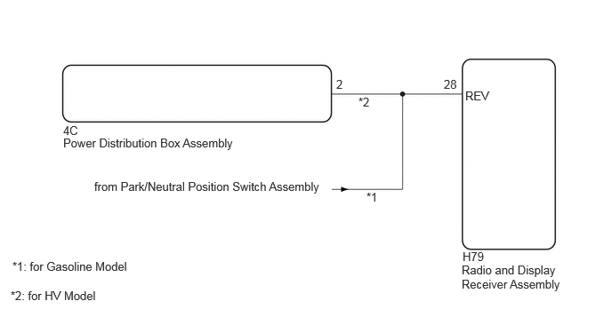
PROCEDURE
Move the shift lever to R and check if the back-up lights come on.
- OK:
The back-up lights come on.
- Result:
Proceed to OK NG
OK
NG
Disconnect the H79 radio and display receiver assembly connector.
Measure the voltage according to the value(s) in the table below.
- Standard Voltage:
Tester Connection Switch Condition Specified Condition Click Location & Routing(H79)Location & Routingewd_type=routing;type=c;code=H79
Click Connector(H79)Instrument Panel>Instrument Panel Wire / Speaker Wire>Radio & Display Receiver Assemblyewd_type=component;type=c;code=H79;pinno=28
H79-28 (REV) - Body ground Ignition switch ON
Shift lever in R11 to 14 V H79-28 (REV) - Body ground Ignition switch ON
Shift lever not in RBelow 1 V
- Result:
Result Proceed to OK A NG (for Gasoline Model) B NG (for HV Model) C
A
B
C
Disconnect the H79 radio and display receiver assembly connector.
Disconnect the 4C power distribution box assembly connector.
Measure the resistance according to the value(s) in the table below.
- Standard Voltage:
Tester Connection Condition Specified Condition Click Location & Routing(H79)Location & Routingewd_type=routing;type=c;code=H79
Click Connector(H79)Instrument Panel>Instrument Panel Wire / Speaker Wire>Radio & Display Receiver Assemblyewd_type=component;type=c;code=H79;pinno=28
H79-28 (REV) - 4C-2 Always Below 1 Ω H79-28 (REV) or 4C-2 - Body ground Always 10 kΩ or higher
- Result:
Proceed to OK NG
OK
NG