FRONT SUSPENSION FRONT SHOCK ABSORBER INSTALLATION
CAUTION / NOTICE / HINT
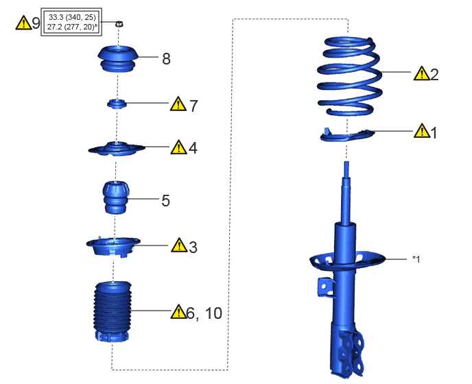
| Procedure | Part Name Code | 
|

|

|
|
|---|---|---|---|---|---|
| 1 | FRONT LOWER COIL SPRING INSULATOR | 48158C | ( ) |
- | - |
| 2 | FRONT COIL SPRING | 48132 | ()
|
- | - |
| 3 | FRONT UPPER COIL SPRING INSULATOR | 48157C | ()
|
- | - |
| 4 | UPPER FRONT COIL SPRING SEAT | 48471C | ()
|
- | - |
| 5 | FRONT SPRING BUMPER | 48331C | - | - | - |
| 6 | INSTALL FRONT NO. 1 SHOCK ABSORBER DUST COVER | 48559B | ()
|
- | - |
| 7 | STRUT MOUNTING BEARING | 48619A | ()
|
- | - |
| 8 | FRONT SUSPENSION SUPPORT SUB-ASSEMBLY | 48609 | - | - | - |
| 9 | FRONT SUPPORT TO FRONT SHOCK ABSORBER NUT | 48609E | ()
|
- | - |
| 10 | CONNECT FRONT NO. 1 SHOCK ABSORBER DUST COVER | 48559B | ()
|
- | - |
| *1 | FRONT SHOCK ABSORBER ASSEMBLY | - | - |

|
Tightening torque for "Major areas involving basic vehicle performance such as moving/turning/stopping" : N*m (kgf*cm, ft.*lbf) | * | For use with SST |
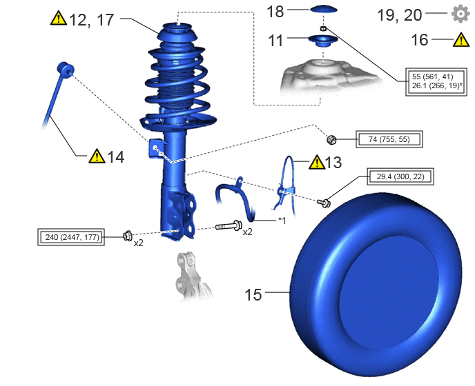
| Procedure | Part Name Code |
|
|
|
|
|---|---|---|---|---|---|
| 11 | FRONT NO. 2 SUSPENSION SUPPORT | 48682B | - | - | - |
| 12 | FRONT SHOCK ABSORBER WITH COIL SPRING | - | ()
|
- | - |
| 13 | FRONT SPEED SENSOR | 89543 | ()
|
- | - |
| 14 | FRONT STABILIZER LINK ASSEMBLY | 48810 | ()
|
- | - |
| 15 | FRONT WHEEL | - | - | - | - |
| 16 | STABILIZE SUSPENSION | - | ()
|
- | - |
| 17 | FULLY TIGHTEN FRONT SHOCK ABSORBER WITH COIL SPRING | - | ()
|
- | - |
| 18 | FRONT SUSPENSION SUPPORT DUST COVER | 48684B | - | - | - |
| 19 | INSPECT AND ADJUST FRONT WHEEL ALIGNMENT | - | - | - | ()
|
| 20 | PERFORM INITIALIZATION | - | - | - | ()
|
| *1 | FRONT SHOCK ABSORBER ASSEMBLY | - | - |
|
|
Tightening torque for "Major areas involving basic vehicle performance such as moving/turning/stopping" : N*m (kgf*cm, ft.*lbf) | * | For use with SST |
CAUTION / NOTICE / HINT
- HINT:
- ·
Use the same procedure for the RH side and LH side.
·The following procedure is for the LH side.
PROCEDURE

 48158C
1.INSTALL FRONT LOWER COIL SPRING INSULATOR
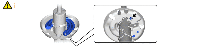

|
Positioning Pin | - | - |
Install the front lower coil spring insulator to the front shock absorber assembly.
- NOTICE:
-
When installing the front lower coil spring insulator, insert the positioning pin of the spring seat into the hole of the front lower coil spring insulator.
48132
2.INSTALL FRONT COIL SPRING
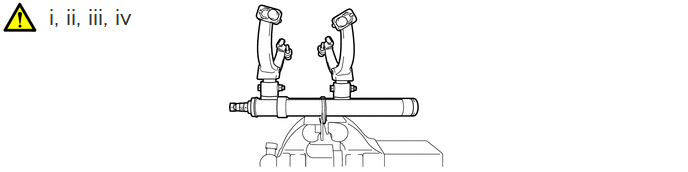
Secure SST in a vise.
- SST
- 09727-30022 (09727-00010, 09727-00022, 09727-00031)
Attach the hooks of each SST arm across the diameter of the front coil spring.
- CAUTION:
- ·
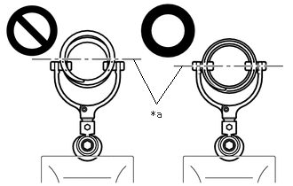 1.563,0.698 1.833,1.219 1.833,1.219 2.135,0.771 false 1.771,1.271 2.083,1.469 0.313,0.198 10 false *a
*a Front Coil Spring Diameter
Do not perform the work without checking to make sure that the claws of the hooks are securely engaged.
·It could cause the hook to slip off and the spring to fly out, which could result in an injury.
·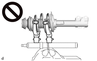
Do not install SST to the front coil spring unless its top and bottom hook distance is set to the widest condition.
·It could cause the hook to slip off and the spring to fly out, which could result in an injury.
·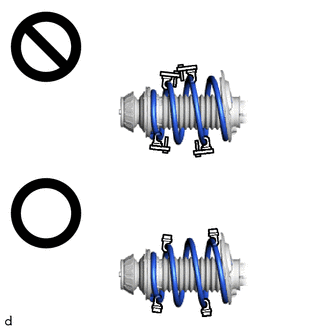
Do not install SST when the distances between the SST arms or the number of coils of the coil spring between the hooks are not the same.
·It could cause the hook to slip off and the spring to fly out, which could result in an injury.
Install the stopper pins to the hooks of SST.
- CAUTION:
- ·
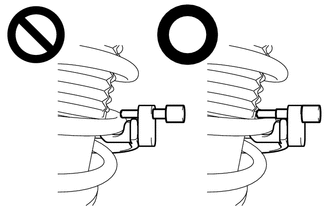
Do not perform the work if the stopper pin is not securely installed.
·It could cause the hook to slip off and the spring to fly out, which could result in an injury.
Using SST, compress the front coil spring.
- CAUTION:
- ·
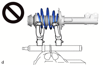
While compressing the spring, if the front coil spring starts to bend into a bow shape, do not continue the work.
·It could cause the hook to slip off and the spring to fly out, which could result in an injury.
·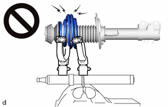
Do not compress the springs so far that the coils of the springs touch each other.
·It could cause the hook to slip off and the spring to fly out, which could result in an injury.
·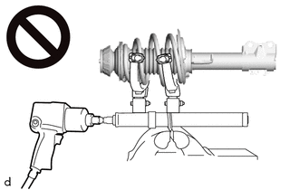
Do not use an impact wrench.
·The threads may be stripped, or the sudden compression may result in slack that causes the hooks to slip off, causing the spring to fly out and possibly resulting in injury.
· 1.042,3.063 1.698,3.063 false 0.74,2.979 1.052,3.135 0.313,0.156 10 false SST
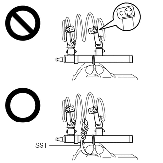
If a stopper pin touches the coil spring while using SST, remove the stopper pin and continue with the procedure.
·If a stopper pin is removed, install a coil spring stopper belt as shown in the illustration.
·If a hook disengages from the coil spring, the coil spring may fly out, resulting in injury.
- SST
- 09727-00110
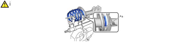
| *a | End of the Front Coil Spring | - | - |
Install the front coil spring to the front shock absorber assembly.
- NOTICE:
-
Make sure to fit the end of the front coil spring that has the smaller diameter into the depression of the front lower coil spring insulator.
48157C
3.INSTALL FRONT UPPER COIL SPRING INSULATOR
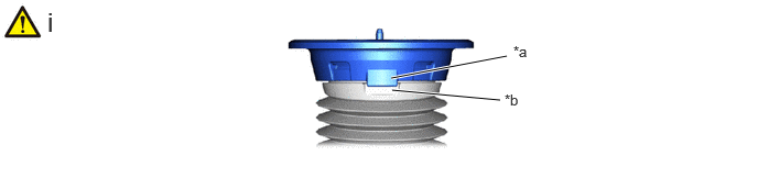
| *a | Positioning Tab | *b | Positioning Indentation |
Install the front upper coil spring insulator to the front No. 1 shock absorber dustcover so that the positioning tab of the front upper coil spring insulator is aligned with the positioning indentation of the front No. 1 shock absorber dustcover.
48471C
4.INSTALL FRONT UPPER COIL SPRING SEAT
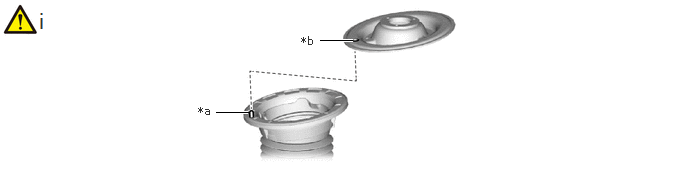
| *a | Positioning Pin | *b | Installation Hole |
Install the front upper coil spring seat to the front upper coil spring insulator.
- NOTICE:
-
When installing the front upper coil spring seat, fit the front upper coil spring insulator to the depression of the front upper coil spring seat and insert the positioning pin into the hole.
48331C
5.INSTALL FRONT SPRING BUMPER
48559B
6.INSTALL FRONT NO. 1 SHOCK ABSORBER DUST COVER
|
|
|
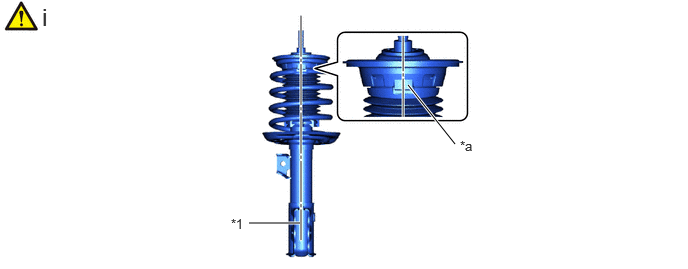
| *1 | Shock Absorber Assembly Lower Bracket | - | - |
| *a | Positioning Portions | - | - |
Align the positioning portions of the front No. 1 shock absorber dust cover and the front upper coil spring insulator with the center of the shock absorber assembly lower bracket and install them.
48619A
7.INSTALL STRUT MOUNTING BEARING
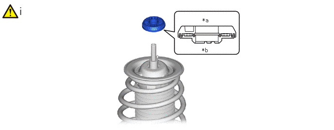
| *a | Upper Side | *b | Lower Side |
Install the strut mounting bearing to the front upper coil spring seat.
- NOTICE:
- ·
Do not install the strut mounting bearing upside down.
·Check that the strut mounting bearing are not damaged or missing.
48609
8.INSTALL FRONT SUSPENSION SUPPORT SUB-ASSEMBLY
48609E
9.INSTALL FRONT SUPPORT TO FRONT SHOCK ABSORBER NUT
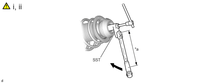
| *a | Torque Wrench Fulcrum Length | - | - |
Using SST and a 6 mm hexagon socket wrench, fix the front shock absorber rod and tighten the front support to front shock absorber nut.
- SST
- 09729-97202
- Torque:
- Specified tightening torque : 33.3 N*m (340 kgf*cm, 25 ft.*lbf)
- NOTICE:
-
Check that front coil spring is not contacting front upper coil spring insulator.
- HINT:
- ·
Calculate the torque wrench reading when changing the fulcrum length of the torque wrench.
Click hereGeneral>INTRODUCTION>REPAIR INSTRUCTION>PRECAUTION
·When using SST (fulcrum length of 40 mm (1.57 in.)) + torque wrench (fulcrum length of 180 mm (7.09 in.)): 27.2 N*m (277 kgf*cm, 20 ft.*lbf)
Remove SST from the front coil spring.
- NOTICE:
- ·
Check that front coil spring is installed so that it is aligned with the level difference of front lower coil spring insulator.
·Do not use an impact wrench. It will damage SST.]
48559B
10.CONNECT FRONT NO. 1 SHOCK ABSORBER DUST COVER
|
|
|
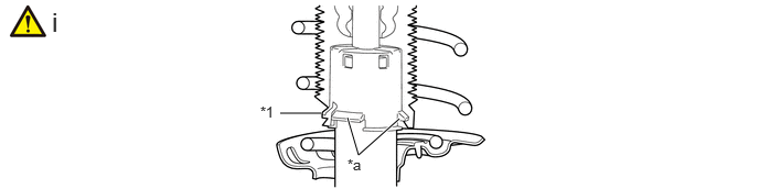
| *1 | Front No. 1 Shock Absorber Dust Cover | - | - |
| *a | Claw | - | - |
Connect the end of the front No. 1 shock absorber dust cover with the claws of the front shock absorber with coil spring.
48682B
11.INSTALL FRONT NO. 2 SUSPENSION SUPPORT
12.INSTALL FRONT SHOCK ABSORBER WITH COIL SPRING
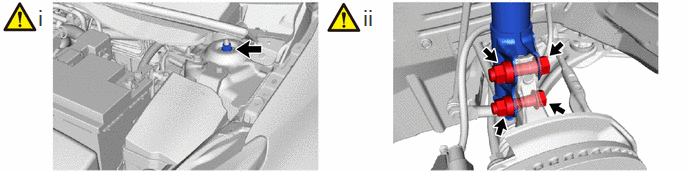
Temporarily install the front No. 2 suspension support and front shock absorber with coil spring to the vehicle with the nut.
Install the front shock absorber with coil spring to the steering knuckle with the 2 bolts and 2 nuts.
- Torque:
- 240 N*m (2447 kgf*cm, 177 ft.*lbf)
- NOTICE:
-
When installing the nuts, keep the bolts from rotating.
- HINT:
-
The bolts can be installed in either direction, however, make sure that they are both installed in the same direction.
89543
13.INSTALL FRONT SPEED SENSOR
|
|
|
- Torque:
- 29.4 N*m (300 kgf*cm, 22 ft.*lbf)
48810
14.INSTALL FRONT STABILIZER LINK ASSEMBLY
|
|
|
- Torque:
- 74 N*m (755 kgf*cm, 55 ft.*lbf)
15.INSTALL FRONT WHEEL
16. STABILIZE SUSPENSION
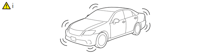
Press down on the vehicle several times to stabilize the suspension.
17.FULLY TIGHTEN FRONT SHOCK ABSORBER WITH COIL SPRING
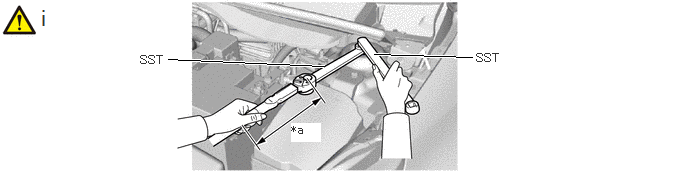
| *a | Torque Wrench Fulcrum Length | - | - |
Using SST, fix the front shock absorber rod and tighten the nut.
- SST
- 09729-00170
09729-38060
- Torque:
- Specified tightening torque : 55 N*m (561 kgf*cm, 41 ft.*lbf)
- HINT:
- ·
Calculate the torque wrench reading when changing the fulcrum length of the torque wrench.
Click hereGeneral>INTRODUCTION>REPAIR INSTRUCTION>PRECAUTION
·When using SST (fulcrum length of 200 mm (7.87 in.)) + torque wrench (fulcrum length of 180 mm (7.09 in.)): 26.1 N*m (266 kgf*cm, 19 ft.*lbf)
48684B
18.INSTALL FRONT SUSPENSION SUPPORT DUST COVER
19.INSPECT AND ADJUST FRONT WHEEL ALIGNMENT
20.PERFORM INITIALIZATION
| Parking support brake system | ()
|
| Parking assist monitor system | ()
|
| Panoramic view monitor system | ()
|