Home › Suspension › ALIGNMENT / HANDLING DIAGNOSIS › REAR WHEEL ALIGNMENT (for AWD) › 2020.08–2021.07
RM3700E _53 Suspension _093738 ALIGNMENT / HANDLING DIAGNOSIS _0441875 REAR WHEEL ALIGNMENT(for AWD) A

ALIGNMENT / HANDLING DIAGNOSIS  REAR WHEEL ALIGNMENT(for AWD)  ADJUSTMENT  


CAUTION / NOTICE / HINT

The necessary procedures (adjustment, calibration, initialization, or registration) that must be performed after completing the rear wheel alignment procedure are shown below.

Necessary Procedure After Parts Removed/Installed/Replaced
Replacement Part or Procedure Necessary Procedure Effect/Inoperative when not Performed Link
Rear wheel alignment adjustment for HV Model:
1.

Perform "Reset Memory"

2.

Perform calibration (linear solenoid valve offset learning, SM solenoid valve offset learning, brake pedal stroke sensor assembly zero point calibration, system information memorization, and yaw rate and acceleration sensor zero point calibration)


·

DTCs are stored

·

ABS warning light illuminates

·

Brake system warning light (yellow indicator)

·

Slip indicator light illuminates

·

VSC disabled or malfunctions


(Click here)
for Gasoline Model:
Calibration
·

DTCs are stored

·

ABS warning light illuminates

·

Slip indicator light illuminates

·

VSC disabled or malfunctions


(Click here)

PROCEDURE

Hide 3.INSPECT CAMBER

NOTICE:

Inspect while the vehicle is unloaded.

a.
C107736C19
2.052,1.26 2.375,1.26 false 2.406,1.167 2.656,1.385 0.25,0.219 10 *a
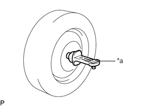
*a Camber-caster-kingpin Gauge


Install a camber-caster-kingpin gauge.


b.

Inspect the camber.

Camber (Unloaded Vehicle):
Tire Size Camber Inclination Right-left Difference
205/65R16
215/50R18
0°11' +/- 0°45' (0.18° +/- 0.75°) 0°45' (0.75°) or less


Hide 4.INSPECT TOE-IN

NOTICE:

Inspect while the vehicle is unloaded.


a.

Bounce the vehicle up and down at the corners to stabilize the suspension.


b.

Release the parking brake and move the shift lever to N


c.

Push the vehicle straight ahead approximately 5 m (16.4 ft.). (Step A)

d.
C188968C02
0.83,0.579 0.83,1.114 false 1.361,0.579 1.361,0.992 1.361,0.992 0.83,0.992 false 0.739,1.134 0.912,1.302 0.173,0.168 10 *a 2.432,1.697 2.607,1.858 0.176,0.161 10 *b 2.522,1.33 2.522,1.671 false
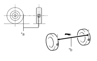
*a Tread Center Mark
*b Dimension B
V100135

Front of the Vehicle


Put tread center marks on the rearmost points of the rear wheels and measure the distance between the marks (dimension B).


e.

Slowly push the vehicle straight ahead to cause the rear wheels to rotate 180°. Use the rear tire valve as a reference point.

HINT:

Do not allow the wheels to rotate more than 180°. If the wheels rotate more than 180°, perform the procedure from step A again.


f.
C188969C02
0.646,1.271 0.646,1.635 false 1.917,0.542 2.052,0.698 0.135,0.156 10 C 3.073,0.552 3.208,0.708 0.135,0.156 10 D 2.5,0.719 2.635,0.875 0.135,0.156 10 A 2.51,1.542 2.646,1.698 0.135,0.156 10 B 0.563,1.656 0.74,1.813 0.177,0.156 10 *a
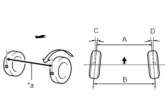
*a Dimension A
V100135

Front of the Vehicle


Measure the distance between the tread center marks on the front of the rear wheels (dimension A).

Toe-in (Unloaded Vehicle)::
Tire Size Specified Condition
205/65R16
215/50R18
C + D: 0°11' +/- 0°10' (0.18° +/- 0.17°)
B - A: 2.3 +/-2.0 mm (0.0906 +/-0.0787 in.)


HINT:

Measure "B - A" only when "C + D" cannot be measured.


Hide 5.ADJUST CAMBER AND TOE-IN

a.
C429784C01
2.365,0.635 1.896,0.458 true 0.76,1.458 1.073,1.531 true 1.677,0.365 1.875,0.552 0.198,0.188 10 true *1 0.51,1.365 0.75,1.552 0.24,0.188 10 true *2 2.906,0.698 3.115,0.885 0.208,0.188 10 true *b 0.75,1.75 0.938,1.927 0.188,0.177 10 true *a 1.469,1.677 1.677,1.865 0.208,0.188 10 true *b 2.135,0.896 2.354,1.094 0.219,0.198 10 true *a
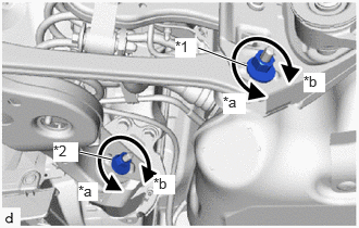
*1 Camber Adjust Cam
*2 Toe Adjust Cam
*a (-)
*b (+)


Loosen the camber adjust cam set nut and toe adjust cam set nut.


b.

Adjust the camber and toe-in by turning the adjust cams.

HINT:

Try to adjust the camber and toe-in to the center of the specified values.


c.

Tighten the camber adjust cam set nut and toe adjust cam set nut.

Torque:
Camber adjust cam set nut : 62 N*m (632 kgf*cm, 46 ft.*lbf)
Toe adjust cam set nut : 80 N*m (816 kgf*cm, 59 ft.*lbf)


d.

How to read the adjusting chart (using examples).
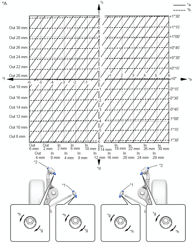
C449029C01
1.729,6.115 1.417,5.927 false 2.646,6.958 2.417,6.76 false 4.75,6.75 4.5,6.948 false 5.76,6.031 5.427,6.125 false 2.271,6.677 2.583,6.833 0.313,0.156 10 false *1 5.823,5.958 6.135,6.115 0.313,0.156 10 false *2 0.073,0.021 0.385,0.281 0.313,0.26 12 false *A 6.844,0.271 7.156,0.427 0.313,0.156 10 false *b 6.844,0.083 7.156,0.24 0.313,0.156 10 false *a 3.667,0 3.979,0.156 0.313,0.156 10 false *c 3.552,6.063 3.865,6.219 0.313,0.156 10 false *d 6.885,2.813 7.156,2.99 0.271,0.177 10 false *e 0.083,2.792 0.396,2.948 0.313,0.156 10 false *f 1.438,8.323 1.76,8.594 0.323,0.271 10 false *g 0.635,7.74 0.948,7.896 0.313,0.156 10 false *h 3.083,8.323 3.417,8.583 0.333,0.26 10 false *g 4.76,8.365 5.073,8.521 0.313,0.156 10 false *h 6.417,8.375 6.729,8.531 0.313,0.156 10 false *h 2.281,7.771 2.552,8.042 0.271,0.271 10 false *h 3.917,7.771 4.25,7.99 0.333,0.219 10 false *g 5.583,7.708 5.896,7.906 0.313,0.198 10 false *g 4.75,6.667 5.063,6.823 0.313,0.156 10 false *1 1.24,5.833 1.552,5.99 0.313,0.156 10 false *2 1.063,5.219 1.375,5.375 0.313,0.156 10 true Out 0.333,4.896 1.083,5.083 0.75,0.188 10 false Out 8 mm 1.563,5.219 1.875,5.375 0.313,0.156 10 true Out 5.771,5.229 6.083,5.385 0.313,0.156 10 true In 3.583,2.833 3.833,3 0.25,0.167 10 true 0 3.583,3.167 3.833,3.333 0.25,0.167 10 true -1 3.583,3.583 3.833,3.75 0.25,0.167 10 true -2 3.583,3.917 3.833,4.083 0.25,0.167 10 true -3 3.583,4.333 3.833,4.5 0.25,0.167 10 true -4 3.583,4.667 3.833,4.833 0.25,0.167 10 true -5 3.542,5.094 3.792,5.26 0.25,0.167 10 true -6 3.583,2.417 3.833,2.583 0.25,0.167 10 true 1 3.583,2.083 3.833,2.25 0.25,0.167 10 true 2 3.583,1.25 3.833,1.417 0.25,0.167 10 true 4 3.583,0.917 3.833,1.083 0.25,0.167 10 true 5 3.583,1.667 3.833,1.833 0.25,0.167 10 true 3 3.583,0.5 3.833,0.667 0.25,0.167 10 true 6 3.083,2.917 3.333,3.083 0.25,0.167 10 true -1 2.667,2.917 2.917,3.083 0.25,0.167 10 true -2 2.25,2.917 2.5,3.083 0.25,0.167 10 true -3 1.833,2.917 2.083,3.083 0.25,0.167 10 true -4 1.417,2.917 1.667,3.083 0.25,0.167 10 true -5 1,2.917 1.25,3.083 0.25,0.167 10 true -6 4,2.667 4.167,2.833 0.167,0.167 10 true 1 4.417,2.667 4.583,2.833 0.167,0.167 10 true 2 4.833,2.667 5,2.833 0.167,0.167 10 true 3 5.25,2.667 5.417,2.833 0.167,0.167 10 true 4 5.667,2.667 5.833,2.833 0.167,0.167 10 true 5 6.146,2.667 6.313,2.833 0.167,0.167 10 true 6 6.25,2.781 6.583,2.948 0.333,0.167 10 true +0° 5.25,5.219 5.563,5.375 0.313,0.156 10 true In 4.188,5.219 4.5,5.375 0.313,0.156 10 true In 4.698,5.229 5.01,5.385 0.313,0.156 10 true In 3.104,5.219 3.417,5.375 0.313,0.156 10 true In 3.667,5.25 3.979,5.406 0.313,0.156 10 true In 2.104,5.219 2.417,5.375 0.313,0.156 10 true In 2.583,5.219 2.896,5.375 0.313,0.156 10 true In 0.333,4.563 1.167,4.75 0.833,0.188 10 false Out 10 mm 0.333,4.167 1.167,4.354 0.833,0.188 10 false Out 12 mm 0.333,3.833 1.167,4.021 0.833,0.188 10 false Out 14 mm 0.333,3.479 1.167,3.667 0.833,0.188 10 false Out 16 mm 0.333,3.083 1.167,3.271 0.833,0.188 10 false Out 18 mm 0.333,2.677 1.167,2.865 0.833,0.188 10 false Out 20 mm 0.333,2.354 1.167,2.542 0.833,0.188 10 false Out 22 mm 0.333,1.99 1.167,2.177 0.833,0.188 10 false Out 24 mm 0.333,1.292 1.167,1.479 0.833,0.188 10 false Out 28 mm 0.333,1.646 1.167,1.833 0.833,0.188 10 false Out 26 mm 0.333,0.927 1.167,1.115 0.833,0.188 10 false Out 30 mm 1.073,5.344 1.552,5.5 0.479,0.156 10 false 6 mm 1.583,5.344 2.063,5.5 0.479,0.156 10 false 2 mm 2.104,5.333 2.583,5.49 0.479,0.156 10 false 2 mm 2.583,5.333 3.063,5.49 0.479,0.156 10 false 6 mm 3.104,5.344 3.583,5.5 0.479,0.156 10 false 10 mm 3.667,5.375 4.146,5.531 0.479,0.156 10 false 14 mm 4.698,5.344 5.177,5.5 0.479,0.156 10 false 22 mm 4.188,5.333 4.667,5.49 0.479,0.156 10 false 18 mm 5.25,5.344 5.729,5.5 0.479,0.156 10 false 26 mm 5.771,5.344 6.25,5.5 0.479,0.156 10 false 30 mm 1.271,5.51 1.583,5.667 0.313,0.156 10 true Out 1.854,5.51 2.167,5.667 0.313,0.156 10 true In 2.354,5.51 2.667,5.667 0.313,0.156 10 true In 2.833,5.51 3.146,5.667 0.313,0.156 10 true In 3.417,5.51 3.729,5.667 0.313,0.156 10 true In 3.938,5.51 4.25,5.667 0.313,0.156 10 true In 4.5,5.51 4.813,5.667 0.313,0.156 10 true In 5,5.51 5.313,5.667 0.313,0.156 10 true In 5.583,5.51 5.896,5.667 0.313,0.156 10 true In 1.302,5.667 1.781,5.823 0.479,0.156 10 true 4 mm 1.854,5.667 2.333,5.823 0.479,0.156 10 true 0 mm 2.354,5.677 2.833,5.833 0.479,0.156 10 true 4 mm 2.854,5.677 3.333,5.833 0.479,0.156 10 true 8 mm 3.438,5.667 3.917,5.823 0.479,0.156 10 true 12 mm 3.917,5.667 4.396,5.823 0.479,0.156 10 true 16 mm 4.5,5.667 4.979,5.823 0.479,0.156 10 true 20 mm 5.021,5.667 5.5,5.823 0.479,0.156 10 true 24 mm 5.583,5.667 6.063,5.823 0.479,0.156 10 true 28 mm 6.198,0.51 7.031,0.698 0.833,0.188 10 false +1°30' 6.198,0.906 7.031,1.094 0.833,0.188 10 false +1°15' 6.198,1.25 7.031,1.438 0.833,0.188 10 false +1°00' 6.198,1.656 7.031,1.844 0.833,0.188 10 false +0°45' 6.198,2.021 7.031,2.208 0.833,0.188 10 false +0°30' 6.188,2.406 7.021,2.594 0.833,0.188 10 false +0°15' 6.188,3.167 6.688,3.333 0.5,0.167 10 true -0°15' 6.177,3.5 6.677,3.667 0.5,0.167 10 true -0°30' 6.188,3.906 6.688,4.073 0.5,0.167 10 true -0°45' 6.188,4.25 6.688,4.417 0.5,0.167 10 true -1°00' 6.188,4.646 6.688,4.813 0.5,0.167 10 true -1°15' 6.188,5.031 6.688,5.198 0.5,0.167 10 true -1°30'
*A Adjusting Chart - -
*1 Camber Adjust Cam *2 Toe Adjust Cam
*a Toe *b Camber
*c Camber Adjust Cam Graduation (+) *d Camber Adjust Cam Graduation (-)
*e Toe Adjust Cam Graduation (+) *f Toe Adjust Cam Graduation (-)
*g (+) (Inward) *h (-) (Outward)


i.

Measure the present alignment.

Measurement value (Example):

Camber (LH) Camber (RH) Toe-in (total) Toe-in (each side)
0°15' (0.25°) 0°30' (0.5°) In 8 mm (0.315 in.) In 4 mm (0.157 in.)

Standard value:

Camber Toe-in (total) Toe-in (each side)
0°11' (0.18°) In 2.3 mm (0.0906 in.) In 1.15 mm (0.0453 in.)


ii.

Put a mark (*f) on the adjusting chart to indicate the measurement value for this example.


iii.

Put a mark (*e) on the adjusting chart to indicate the standard value for this example.
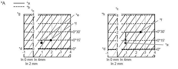
C449031C01
5.698,1.26 6.365,0.833 true 6.573,1.823 5.042,1.74 true 2.948,0.958 2.063,1.594 true 2.99,0.604 1.646,1.698 true 1.073,0.042 1.385,0.24 0.313,0.198 10 false *a 1.073,0.208 1.385,0.406 0.313,0.198 10 false *b 1.26,0.354 1.573,0.552 0.313,0.198 10 false *c 4.115,1.896 4.427,2.094 0.313,0.198 10 false *d 4.656,0.271 4.969,0.469 0.313,0.198 10 false *c 0.76,1.885 1.073,2.083 0.313,0.198 10 false *d 3.052,0.521 3.365,0.719 0.313,0.198 10 false *e 2.99,0.875 3.302,1.073 0.313,0.198 10 false *f 6.427,0.719 6.74,0.917 0.313,0.198 10 false *f 6.656,1.729 6.969,1.927 0.313,0.198 10 false *e 0.688,0.469 1,0.667 0.313,0.198 10 false *g 4.094,0.49 4.406,0.688 0.313,0.198 10 false *h 1.302,1.896 1.531,2.063 0.229,0.167 10 true 0 1.292,1.563 1.521,1.729 0.229,0.167 10 true 1 1.313,1.198 1.542,1.365 0.229,0.167 10 true 2 1.302,0.5 1.531,0.667 0.229,0.167 10 true 4 1.302,0.875 1.531,1.042 0.229,0.167 10 true 3 0.906,2.031 1.135,2.198 0.229,0.167 10 true -1 2.042,2.031 2.24,2.219 0.198,0.188 10 true 2 2.406,2.021 2.604,2.208 0.198,0.188 10 true 3 2.802,2.021 3,2.208 0.198,0.188 10 true 4 4.25,2.073 4.479,2.24 0.229,0.167 10 true -1 1.656,2.031 1.854,2.219 0.198,0.188 10 true 1 5.052,2.052 5.25,2.24 0.198,0.188 10 true 1 5.448,2.052 5.646,2.24 0.198,0.188 10 true 2 5.802,2.042 6,2.229 0.198,0.188 10 true 3 6.198,2.042 6.396,2.229 0.198,0.188 10 true 4 4.667,1.917 4.896,2.083 0.229,0.167 10 true 0 4.688,1.573 4.885,1.76 0.198,0.188 10 true 1 4.688,1.229 4.885,1.417 0.198,0.188 10 true 2 4.688,0.885 4.885,1.073 0.198,0.188 10 true 3 4.688,0.542 4.885,0.729 0.198,0.188 10 true 4 4.292,2.333 4.875,2.5 0.583,0.167 10 true In 0 mm 4.833,2.333 5.417,2.5 0.583,0.167 10 true In 4mm 4.458,2.5 5.104,2.667 0.646,0.167 10 true In 2 mm 0.833,2.333 1.417,2.5 0.583,0.167 10 true In 0 mm 1.375,2.333 1.958,2.5 0.583,0.167 10 true In 4mm 1.021,2.5 1.667,2.667 0.646,0.167 10 true In 2 mm 2.854,1.208 3.438,1.375 0.583,0.167 10 true +0°30' 6.25,1.552 6.833,1.719 0.583,0.167 10 true +0°15' 2.854,1.896 3.438,2.063 0.583,0.167 10 true +0° 6.25,1.917 6.833,2.083 0.583,0.167 10 true +0° 2.865,1.542 3.448,1.708 0.583,0.167 10 true +0°15' 6.25,1.198 6.833,1.365 0.583,0.167 10 true +0°30' 0.031,0.021 0.396,0.271 0.365,0.25 12 false *A
*A Example - -
*a Toe *b Camber
*c Camber Adjust Cam Graduation *d Toe Adjust Cam Graduation
*e Standard Value *f Measurement Value
*g LH Side *h RH Side


iv.

As shown in the example chart, read the distance from the marked point (*f) to (*e), and adjust the camber adjust cam and/or toe adjust cam accordingly.

Amount to turn adjust cams (by graduation):

LH Side RH Side
Camber Adjust Cam Toe Adjust Cam Camber Adjust Cam Toe Adjust Cam
(-) (Outward) 0.1 (-) (Outward) 1.1 (-) (Outward) 1.1 (-) (Outward) 1.8


Hide 6.ALIGN FRONT WHEELS FACING STRAIGHT AHEAD

Hide 7.INSPECT AND ADJUST HEADLIGHT AIMING

HINT:

These procedures are to be performed when suspension or tires components have been removed or replaced.