Home › Engine / Hybrid System › M15A-FKS (STARTING) › STARTER › 2020.08–2021.07
RM3700E _51 Engine / Hybrid System _093780 M15A-FKS STARTING _0442169 STARTER A

M15A-FKS STARTING  STARTER  REASSEMBLY  


CAUTION / NOTICE / HINT
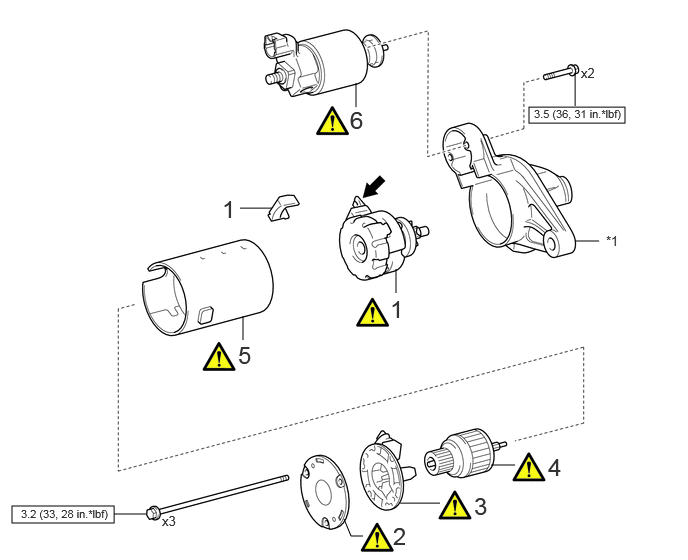
COMPONENTS (REASSEMBLY)
A461650N03
5.51,1.115 6.51,1.281 1,0.167 0.125,5.271 1.188,5.448 1.063,0.177 5.99,1.104 5.99,0.771 false 3.708,1.115 3.708,0.865 false 2.531,3.542 2.531,3.292 false 4.125,3.052 4.125,2.802 false 1.188,5.354 1.521,5.354 false 3.583,5.406 3.656,5.583 3.656,5.583 3.781,5.583 false 4.167,5.24 4.583,5.24 false 5.115,4.844 5.365,4.844 false 2.5,2.167 2.833,2.167 false 5.99,2.51 6.24,2.51 false 2.313,2.031 2.594,2.385 0.281,0.354 18 false 1 3.646,1.104 3.927,1.458 0.281,0.354 18 false 6 2.479,3.552 2.76,3.906 0.281,0.354 18 false 5 4.063,3.073 4.344,3.427 0.281,0.354 18 false 1 4.094,5.438 4.375,5.792 0.281,0.354 18 false 2 4.938,5.125 5.219,5.479 0.281,0.354 18 false 3 5.708,4.719 5.99,5.073 0.281,0.354 18 false 4 1.688,5.344 1.938,5.542 0.25,0.198 10 false x3 6.052,0.677 6.302,0.875 0.25,0.198 10 false x2 5.563,1.115 6.677,1.375 1.115,0.26 8 false 3.5 (36, 31 in.*lbf) 0.219,5.281 1.781,5.49 1.563,0.208 8 false 3.2 (33, 28 in.*lbf) 6.313,2.427 6.594,2.781 0.281,0.354 10 false *1

Procedure Part Name Code
Z101186

Z101188

Z101187

1 STARTER CENTER BEARING CLUTCH SUB-ASSEMBLY 28021 (Click here) - -
2 STARTER COMMUTATOR END FRAME ASSEMBLY - (Click here) - -
3 STARTER BRUSH HOLDER ASSEMBLY - (Click here) - -
4 STARTER ARMATURE ASSEMBLY 28160 (Click here) - -
5 STARTER YOKE ASSEMBLY - (Click here) - -
6 MAGNET STARTER SWITCH ASSEMBLY 28226C (Click here) - -

V100146

N*m (kgf*cm, ft.*lbf): Specified torque
V100135

High-temperature grease
*1 STARTER DRIVE HOUSING ASSEMBLY - -

PROCEDURE

Hide 28021 1.INSTALL STARTER CENTER BEARING CLUTCH SUB-ASSEMBLY

a.
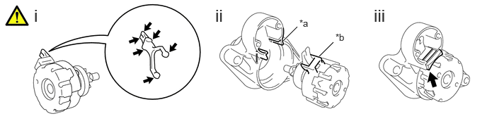
A461638C02
4.167,0.604 4.375,0.396 true 4.698,0.833 4.906,0.625 true 3.75,0.688 4.031,1.042 0.281,0.354 18 false i 3.167,0.083 3.417,0.417 0.25,0.333 18 false ii 0.5,0.083 0.75,0.417 0.25,0.333 18 false i 5.5,0.083 5.75,0.417 0.25,0.333 18 false iii 4.406,0.26 4.656,0.594 0.25,0.333 10 false *a 4.938,0.469 5.188,0.802 0.25,0.333 10 false *b
*a Cutout *b Protrusion
V100135

High-temperature Grease - -


i.

Apply high-temperature grease to the pinion drive lever.

HINT:

Apply approximately 0.1 g of high-temperature grease to each section.


ii.

Align the cutout of the starter drive housing assembly with the protrusion of the starter center bearing clutch sub-assembly and install the starter center bearing clutch sub-assembly.


iii.

Install the rubber seal to the starter drive housing assembly.


Hide 2.INSTALL STARTER COMMUTATOR END FRAME ASSEMBLY

Z101186

HINT:

If the parts are not aligned correctly, the throughbolt cannot be attached.


a.
A461645C03
3.083,1.188 3.667,0.302 3.667,0.302 2.927,0.542 true 4.635,1.208 5.073,0.198 5.073,0.198 4.229,0.542 true 3.698,0.177 4.01,0.375 0.313,0.198 10 false *a 5.125,0.104 5.438,0.302 0.313,0.198 10 false *b
*a Cutout *b Protrusion


Hide 3.INSTALL STARTER BRUSH HOLDER ASSEMBLY

Hide 28160 4.INSTALL STARTER ARMATURE ASSEMBLY

a.
A461640N02
2.458,0.125 2.74,0.479 0.281,0.354 18 false i

i.

Install the starter yoke assembly while holding down the starter armature assembly and starter brush holder assembly with the handle of a hammer.


Hide 5.INSTALL STARTER YOKE ASSEMBLY

a.
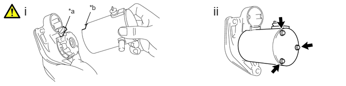
A461641C03
1.354,0.573 1.448,0.333 false 1.781,0.49 1.875,0.25 false 0.5,0.083 0.781,0.438 0.281,0.354 18 false i 4.417,0.083 4.698,0.438 0.281,0.354 18 false ii 1.417,0.146 1.698,0.5 0.281,0.354 10 false *a 1.854,0.073 2.135,0.427 0.281,0.354 10 false *b
*a Cutout *b Protrusion


i.

Align the cutout of the starter yoke assembly with the protrusion of the starter center bearing clutch sub-assembly.


ii.

Install the starter yoke assembly with the 3 through bolts.

Torque:
3.2 N*m (33 kgf*cm, 28 in.*lbf)


Hide 28226B 6.INSTALL MAGNET STARTER SWITCH ASSEMBLY
a.
A461642C02
1.104,0.583 1.354,0.583 false 1.208,1.156 1.354,1.031 false 3.563,2.083 3.667,2.083 false 0.469,0.083 0.75,0.438 0.281,0.354 18 false i 3.219,0.083 3.5,0.438 0.281,0.354 18 false ii 5.719,0.083 6,0.438 0.281,0.354 18 false iii 1.406,0.521 1.688,0.875 0.281,0.354 10 false *1 1.021,1.125 1.302,1.479 0.281,0.354 10 false *2 3.396,2.01 3.677,2.365 0.281,0.354 10 false *a
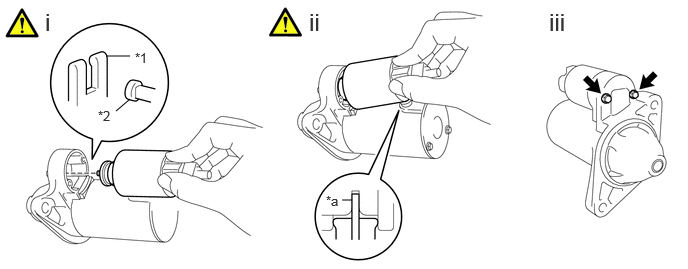
*1 Pinion Drive Lever *2 Hook
*a Terminal C - -


i.

Hang the hook of the magnet starter switch assembly on the pinion drive lever.


ii.

Push down the back of the magnet starter switch assembly and connect it to terminal C.

NOTICE:
·

Connect the magnet starter switch assembly securely to terminal C.

·

Check that the parts are free of foreign matter, oil or grease.


iii.

Install the magnet starter switch assembly with the 2 bolts.

Torque:
3.5 N*m (36 kgf*cm, 31 in.*lbf)