HYBRID / BATTERY CONTROL HYBRID CONTROL SYSTEM Rear Cooling System
DESCRIPTION
The cause of this malfunction may be the cooling system.
Check whether the rear inverter cooling fan or cooling fins are blocked, and the rear inverter cooling fan operating condition.
| Area | Inspection |
|---|---|
| Rear inverter cooling fan | Check for rear inverter cooling fan malfunction or abnormal operation due to clogging. |
| Cooling fins | Check for overheating due to clogged cooling fins. |
| Data List |
|---|
| Ambient Temperature |
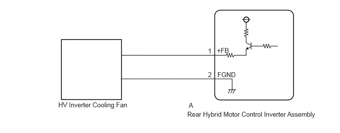
WIRING DIAGRAM
CAUTION / NOTICE / HINT
This diagnostic procedure is referenced to in the diagnostic procedure of several DTCs.
If the result of this diagnostic procedure is normal, proceed as directed in the procedure for the DTC.
- CAUTION:
- ·
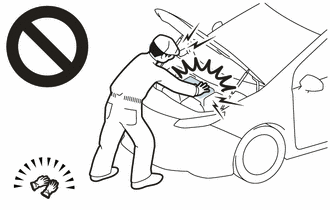
Before the following operations are conducted, take precautions to prevent electric shock by turning the ignition switch off, wearing insulated gloves, and removing the service plug grip from HV battery.
-Inspecting the high-voltage system
-Disconnecting the low voltage connector of the hybrid motor control inverter assembly and rear hybrid motor control inverter assembly*
*: for AWD
-Disconnecting the low voltage connector of the HV battery
·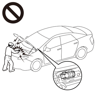
To prevent electric shock, make sure to remove the service plug grip to cut off the high voltage circuit before servicing the vehicle.
·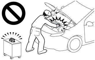
After removing the service plug grip from the HV battery, put it in your pocket to prevent other technicians from accidentally reconnecting it while you are working on the high-voltage system.
·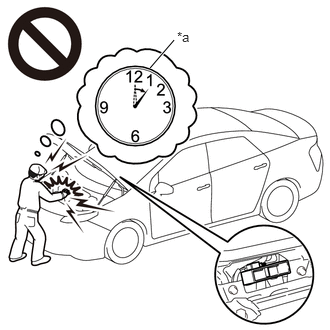 1.563,0.708 1.813,0.417 true 1.844,0.302 2.156,0.5 0.313,0.198 10 false *a
*a Without waiting for 10 minutes
After removing the service plug grip, wait for at least 10 minutes before touching any of the high-voltage connectors or terminals. After waiting for 10 minutes, check the voltage at the terminals in the inspection point in the hybrid motor control inverter assembly and rear hybrid motor control inverter assembly*. The voltage should be 0 V before beginning work.
Click hereEngine / Hybrid System>HYBRID / BATTERY CONTROL>HYBRID CONTROL SYSTEM>PRECAUTION
- HINT:
-
Waiting for at least 10 minutes is required to discharge the high-voltage capacitor inside the hybrid motor control inverter assembly and rear hybrid motor control inverter assembly*.
*: for AWD
- NOTICE:
- ·
After the ignition switch is turned off, there may be a waiting time before disconnecting the auxiliary negative (-) battery terminal.
Click hereGeneral>SETUP>WHEN DISCONNECTING OR RECONNECTING BATTERY TERMINAL>BEFORE DISCONNECTING BATTERY
·When disconnecting and reconnecting the auxiliary battery
Click hereGeneral>SETUP>WHEN DISCONNECTING OR RECONNECTING BATTERY TERMINAL>WORK PROCEDURE
- HINT:
-
When disconnecting and reconnecting the auxiliary battery, there is an automatic learning function that completes learning when the respective system is used.
-
Click hereGeneral>SETUP>WHEN DISCONNECTING OR RECONNECTING BATTERY TERMINAL>AUTOMATIC LEARNING CHART
PROCEDURE
Pre-procedure1
None.
Procedure1
Check the HV inverter cooling fan blockage or clog.
- Specified Condition:
HV inverter cooling fan no blockage or clog.
- Result:
Proceed to OK NG
Post-procedure1
Install the rear No. 1 floor board.
OK
NG
Pre-procedure1
None.
Procedure1
Perform the active test.
- Powertrain > Rear Motor Generator > Active Test
-
Tester Display Rear Inverter Cooling Fan - 50004 396 1
Check that the HV inverter cooling fan operates.
- Result:
Result Proceed to HV inverter cooling fan operates, fan speed is stable and there is no abnormal noise. A HV inverter cooling fan does not operate B HV inverter cooling fan speed is unstable, or there is abnormal noise.
Post-procedure1
Turn the ignition switch off.
Install the rear No. 1 floor board.
A
B
Pre-procedure1
Connect rear hybrid motor control inverter assembly connector.
Remove HV inverter cooling cover from the rear hybrid motor control inverter assembly.
Procedure1
Check the cooling fin blockage or clog
- Specified Condition:
Cooling fin no blockage or clog
- Result:
Proceed to OK NG
Post-procedure1
Install HV inverter cooling cover from the rear hybrid motor control inverter assembly.
Reconnect rear hybrid motor control inverter assembly connector.
OK
NG
- CAUTION:
-
Be sure to wear insulated gloves.
Pre-procedure1
Check that the service plug grip is not installed.
- NOTICE:
-
After removing the service plug grip, do not turn the ignition switch to ON (READY), unless instructed by the repair manual because this may cause a malfunction.
Disconnect the A rear inverter cooling fan connector.
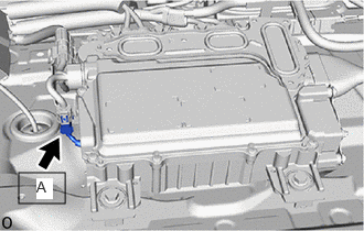
Connect the cable to the negative (-) auxiliary battery terminal.
Procedure1
Perform the active test.
- Powertrain > Rear Motor Generator > Active Test
-
Tester Display Measurement Item Control Range Restrict Condition Rear Inverter Cooling Fan Rear inverter cooling fan can be forced to operate. Stop/Start -
- Powertrain > Rear Motor Generator > Active Test
-
Tester Display Rear Inverter Cooling Fan - 50004 396 1
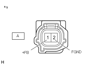
| *a | Front view of wire harness connector
(to Rear Inverter Cooling Fan Connector) |
Check the voltage of connector A (rear inverter cooling fan connection connector) of the rear hybrid motor control inverter assembly.
- Standard Voltage:
Tester Connection Condition Specified Condition A-1 (+FB) - A-2 (FGND) Ignition switch ON, fan operation commanded by Active Test 10 to 12 V Ignition switch ON, fan operation commanded by Active Test 0 to 1.5 V
- Result:
Proceed to OK NG
Post-procedure1
Turn the ignition switch off.
Disconnect the cable to the negative (-) auxiliary battery terminal.
Reconnect the A HV inverter cooling fan connector.
Install the rear No. 1 floor board.
OK
NG