Home › Drivetrain › EC6D (MANUAL TRANSMISSION / TRANSAXLE) › SHIFT AND SELECT LEVER SHAFT › from 2021.07
RM3700E _52 Drivetrain _104886 EC6D MANUAL TRANSMISSION / TRANSAXLE _0480443 SHIFT AND SELECT LEVER SHAFT A

EC6D MANUAL TRANSMISSION / TRANSAXLE  SHIFT AND SELECT LEVER SHAFT  REASSEMBLY  


CAUTION / NOTICE / HINT
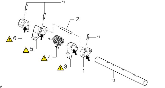
COMPONENTS (REASSEMBLY)
C460800N01
3.625,2.906 3.625,2.49 false 2.885,1.271 3.052,0.854 3.052,0.854 3.219,0.854 false 1.156,0.188 1.156,0.104 1.156,0.104 2.656,0.104 false 1.938,0.552 1.938,0.104 false 3.844,1.615 4.177,1.615 false 2.969,2.906 3.063,2.906 3.063,2.906 3.063,2.542 false 4.938,3.385 4.938,3.052 false 2.281,2.479 2.448,2.479 2.448,2.479 2.448,2.052 false 1.5,2.125 1.594,2.125 1.594,2.125 1.594,1.677 false 0.792,1.667 0.958,1.667 0.958,1.667 0.958,1.188 false 3.563,2.917 3.844,3.271 0.281,0.354 18 false 1 3.302,0.677 3.583,1.031 0.281,0.354 18 false 2 0.573,1.5 0.854,1.854 0.281,0.354 18 false 6 2.698,0 3.01,0.198 0.313,0.198 10 false *1 4.219,1.51 4.531,1.708 0.313,0.198 10 false *1 4.875,3.406 5.188,3.604 0.313,0.198 10 false *2 2.781,2.729 3.063,3.083 0.281,0.354 18 false 3 2.083,2.323 2.365,2.677 0.281,0.354 18 false 4 1.302,1.969 1.583,2.323 0.281,0.354 18 false 5

Procedure Part Name Code
Z101186

Z101188

Z101187

1 SELECT STOPPER BLOCK 33288 (Click here) - -
2 RELEASE HEAD STRAIGHT PIN 33237D - - -
3 RELEASE HEAD 33237 (Click here) - -
4 RELEASE HEAD TORSION SPRING 33237C (Click here) - -
5 FRONT INNER SHIFT LEVER 33926 (Click here) - -
6 INNER NO. 2 SHIFT LEVER 33252A (Click here) - -

*1 SLOTTED SPRING PIN *2 SHIFT AND SELECT LEVER SHAFT
V100135

Gear Oil - -

PROCEDURE

Hide 33288 1.INSTALL SELECT STOPPER BLOCK
a.
C460801C01
4.458,2.865 4.917,3.063 0.458,0.198 10 false (A) 0.51,0.073 0.792,0.427 0.281,0.354 18 false i 4.125,0.063 4.406,0.417 0.281,0.354 18 false ii 2.458,2.365 2.74,2.719 0.281,0.354 18 false iii 5.292,0.365 5.448,0.563 0.156,0.198 10 false A 5.302,1.01 5.458,1.208 0.156,0.198 10 false A 5.458,1.271 6.406,1.729 0.948,0.458 10 false A - A
V100135

Gear Oil - -


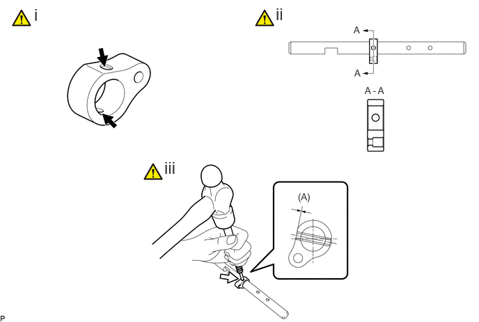
i.

Coat the select stopper block with gear oil.


ii.

Install the select stopper block as shown in the illustration.

NOTICE:

Confirm the installation direction.


iii.

Using a 5 mm pin punch and hammer, install the slotted spring pin to the shift and select lever shaft.

Driven in Depth (A):

-0.2 to 0.8 mm (-0.00787 to 0.03150 in.)


Hide 33237D 2.INSTALL RELEASE HEAD STRAIGHT PIN

a.
C460802


Hide 33237 3.INSTALL RELEASE HEAD

a.
C460803C01
0.49,0.167 0.771,0.521 0.281,0.354 18 false i 3.219,0.167 3.5,0.521 0.281,0.354 18 false ii 3.552,0.667 3.708,0.865 0.156,0.198 10 false A 4.604,0.563 4.76,0.76 0.156,0.198 10 false A 5.948,0.135 6.552,0.427 0.604,0.292 10 false A - A
V100135

Gear Oil - -


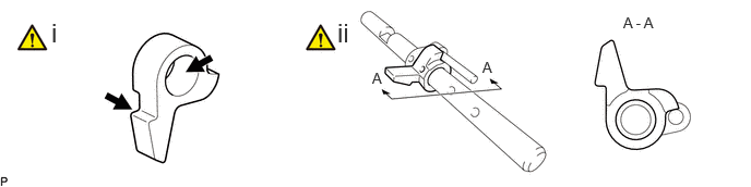
i.

Coat the release head with gear oil.


ii.

Install the release head as shown in the illustration.

NOTICE:

Confirm the installation direction.


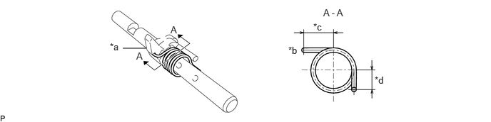
Hide 33237C 4.INSTALL RELEASE HEAD TORSION SPRING

Z101186

NOTICE:

Confirm the installation direction.


a.
C460804C01
1.792,0.708 2.135,0.708 false 1.604,0.604 1.917,0.802 0.313,0.198 10 false *a 1.99,0.74 2.146,0.938 0.156,0.198 10 false A 2.49,0.354 2.646,0.552 0.156,0.198 10 false A 4.719,0.104 5.729,0.531 1.01,0.427 10 false A - A 4.208,0.656 4.521,0.854 0.313,0.198 10 false *b 4.573,0.313 4.885,0.51 0.313,0.198 10 false *c 5.469,1.094 5.781,1.292 0.313,0.198 10 false *d
*a Hook *b Hook Side
*c 14.5 to 15.5 mm (0.571 to 0.610 in.) *d 8.3 to 9.3 mm (0.327 to 0.366 in.)


Hide 33926 5.INSTALL FRONT INNER SHIFT LEVER
a.
C460805C01
2.125,3.729 2.375,3.729 2.375,3.729 2.375,3.823 false 3.24,4.313 3.5,4.313 true 2.875,3.552 3.51,3.552 true 0.427,0.063 0.708,0.417 0.281,0.354 18 false i 2.677,0.042 2.958,0.396 0.281,0.354 18 false ii 4.781,0.073 5.146,0.438 0.365,0.365 18 false iii 3.906,2.5 4.271,2.865 0.365,0.365 18 false v 4.396,2.792 4.854,2.99 0.458,0.198 10 false (A) 0.49,3.573 0.646,3.771 0.156,0.198 10 false A 1.01,4.448 1.167,4.646 0.156,0.198 10 false A 2.698,2.917 3.646,3.177 0.948,0.26 10 false A - A 1.948,3.635 2.26,3.833 0.313,0.198 10 false *1 3.542,4.219 3.854,4.417 0.313,0.198 10 false *2 3.552,3.448 3.865,3.646 0.313,0.198 10 false *1 0.396,2.521 0.677,2.875 0.281,0.354 18 false iv
*1 Release Head Torsion Spring *2 Release Head straight Pin
V100135

Gear Oil
V113147

Turn


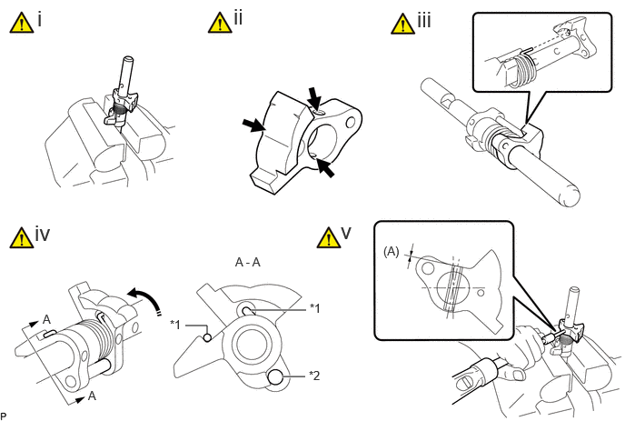
i.

Secure the shift and select lever shaft in a vise between aluminum plates.

NOTICE:

Do not overtighten the vise.


ii.

Coat the front inner shift lever with gear oil.


iii.

Install the front inner shift lever as shown in the illustration.

NOTICE:

Confirm the installation direction.


HINT:

Insert the release head torsion spring to the installation hole of the front inner shift lever.


iv.

Turn the front inner shift lever to align it with the installation surface of the straight pin, and install it.

NOTICE:

Confirm that the front inner shift lever is installed as shown in the illustration.


v.

Using a 5 mm pin punch and hammer, install the slotted spring pin to the shift and select lever shaft.

Driven in Depth (A):

-0.2 to 0.8 mm (-0.00787 to 0.03150 in.)


Hide 33252A 6.INSTALL INNER NO. 2 SHIFT LEVER
a.
C460806C01
0.417,0.104 0.583,0.458 0.167,0.354 18 false i 6.438,1.115 6.823,1.365 0.385,0.25 10 false (A) 3.292,0.104 3.563,0.521 0.271,0.417 18 false ii
V100135

Gear Oil - -


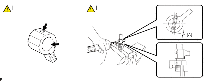
i.

Coat the inner No. 2 shift lever with gear oil.


ii.

Using a 5 mm pin punch and hammer, install the inner No. 2 shift lever and slotted spring pin to the shift and select lever shaft.

Driven in Depth (A):

0 to 0.6 mm (0 to 0.02362 in.)


NOTICE:

Confirm the installation direction.