LIGHTING (EXT) HEADLIGHT ASSEMBLY(for LED Headlight) REASSEMBLY
CAUTION / NOTICE / HINT
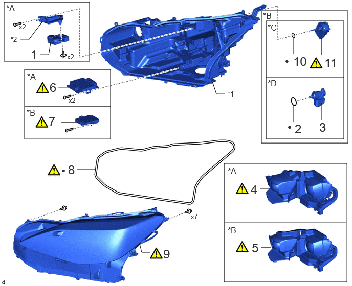
| Procedure | Part Name Code | 
|

|

|
|
|---|---|---|---|---|---|
| 1 | HEADLIGHT LEVELING MOTOR | 85662 | - | - | - |
| 2 | HEADLIGHT LEVELING MOTOR BASE PACKING | 85669 | - | - | - |
| 3 | HEADLIGHT LEVELING MOTOR | 85662 | - | - | - |
| 4 | HEADLIGHT UNIT | 81171A | ( ) |
- | - |
| 5 | HEADLIGHT UNIT | 81171A | ()
|
- | - |
| 6 | LIGHT CONTROL LED ECU | 85967D | ()
|
- | - |
| 7 | LIGHT CONTROL LED ECU | 85967D | ()
|
- | - |
| 8 | HEADLIGHT LENS GASKET | 81132B | ()
|
- | - |
| 9 | HEADLIGHT LENS SUB-ASSEMBLY | 8110B | ()
|
- | - |
| 10 | HEADLIGHT LEVELING MOTOR BASE PACKING | 85669 | - | - | - |
| 11 | HEADLIGHT LEVELING MOTOR | 85662 | ()
|
- | - |
| *A | w/ Adaptive High Beam System | *B | w/o Adaptive High Beam System |
| *C | for TMC Made | *D | for TMMF Made |
| *1 | HEADLIGHT HOUSING SUB-ASSEMBLY | - | - |
| ● | Non-reusable part | - | - |
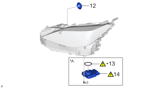
| Procedure | Part Name Code |
|
|
|
|
|---|---|---|---|---|---|
| 12 | NO. 1 HEADLIGHT COVER | 81144 | - | - | - |
| 13 | HEADLIGHT GASKET | 81134 | ()
|
- | - |
| 14 | HEADLIGHT ECU SUB-ASSEMBLY | 81056 | ()
|
- | - |
| *A | w/ Adaptive High Beam System | - | - |
| ● | Non-reusable part | - | - |
CAUTION / NOTICE / HINT
- NOTICE:
- ·
Handle components indoors as much as possible to prevent foreign matter from entering and adhering to headlight assembly components.
·Do not reuse parts which have reduced fastening ability due to thread damage.
·When installing components, make sure that the wire harness is not pinched or pulled.
·Do not use solvent to clean components. Only clean them with a dry cloth.
- HINT:
- ·
Use the same procedure for the RH side and LH side.
·The following procedure is for the LH side.
PROCEDURE

 85662
1.INSTALL HEADLIGHT LEVELING MOTOR (w/ Adaptive High Beam System)
85669
2.INSTALL HEADLIGHT LEVELING MOTOR BASE PACKING (w/o Adaptive High Beam System)
85662
3.INSTALL HEADLIGHT LEVELING MOTOR (w/o Adaptive High Beam System)
81171A
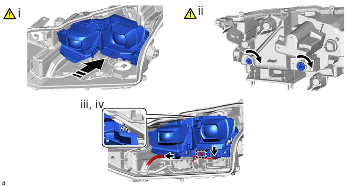
4.INSTALL HEADLIGHT UNIT (w/ Adaptive High Beam System)
|
|
|
- SST
- 09890-47010 (09891-04010, 09891-04020, 09891-04030, 09891-04040)

|
Turn | 
|
Install in this Direction |
Temporarily install the headlight unit to the headlight housing sub-assembly as shown in the illustration.
While holding the headlight unit by hand, turn the 2 aiming screws.
- NOTICE:
-
Turn the aiming screw the same number of times as they were turned during removal.
Engage the clamp and clip.
Connect the 2 connectors.
81171A
5.INSTALL HEADLIGHT UNIT (w/o Adaptive High Beam System)
|
|
|
- SST
- 09890-47010 (09891-04010, 09891-04020, 09891-04030, 09891-04040)
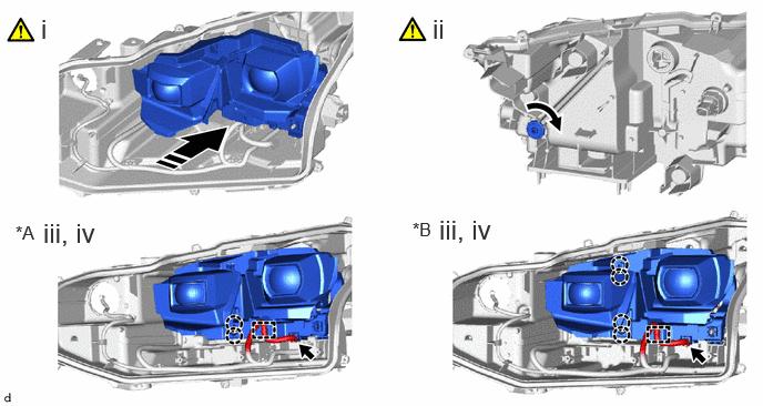
| *A | for TMC Made | *B | for TMMF Made |
|
|
Turn |
|
Install in this Direction |
Temporarily install the headlight unit to the headlight housing sub-assembly as shown in the illustration.
While holding the headlight unit by hand, turn the aiming screw.
- NOTICE:
-
Turn the aiming screw the same number of times as they were turned during removal.
Engage the claws and clamp.
Connect the connector.
85967D
6.INSTALL LIGHT CONTROL LED ECU (w/ Adaptive High Beam System)
|
|
|
85967D
7.INSTALL LIGHT CONTROL LED ECU (w/o Adaptive High Beam System)
|
|
|
81132B
8.INSTALL HEADLIGHT LENS GASKET
|
|
|
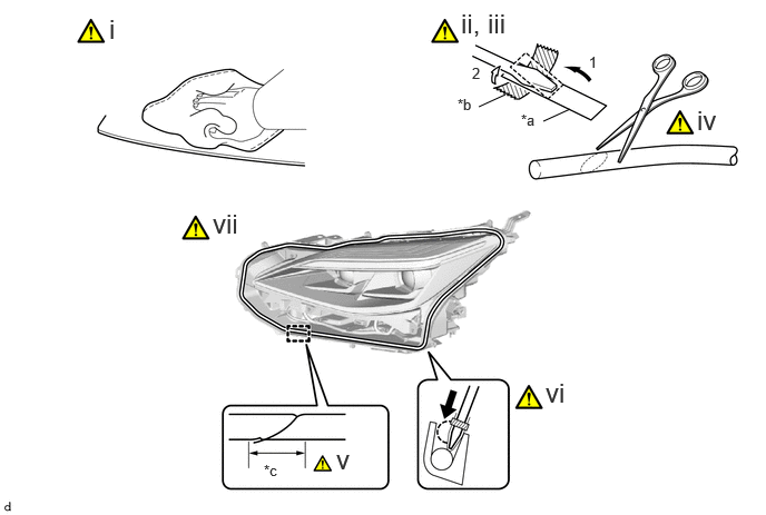
| *a | Release Paper | *b | Tape |
| *c | 20mm | - | - |
Clean the installation groove of the headlight lens sub-assembly.
Partially remove the release paper from a new headlight lens gasket, and cut off a piece of it.
Fold the release paper over the tip of a screwdriver and secure it in place with tape as indicated by the arrows, in the order shown in the illustration.
Using scissors, cut the end of the headlight lens gasket at a 45° angle.
Install a new headlight lens gasket as shown in the illustration.
- NOTICE:
-
Gently install the headlight lens gasket without pulling it.
Using a screwdriver with their tips wrapped with release paper, completely press the headlight lens gasket into the groove to install it.
- NOTICE:
- ·
Gently install the headlight lens gasket without pulling it.
·If the headlight lens gasket is pulled while it is installed, it will not be installed properly.
Check the installation condition of the headlight lens gasket.
- NOTICE:
- ·
Make sure the headlight lens gasket is not protruding and is installed properly.
·Make sure there is no gap between the ends of the headlight lens gasket.
8110B
9.INSTALL HEADLIGHT LENS SUB-ASSEMBLY
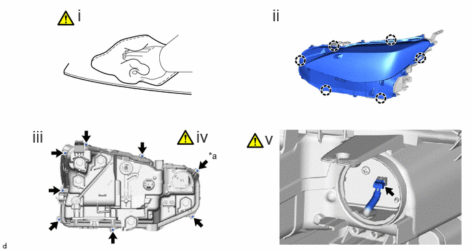
| *a | "TORX" Screw | - | - |
Clean the sealing surface of the headlight lens sub-assembly.
- NOTICE:
- ·
Make sure to wear clean rubber gloves when performing this procedure.
·Do not allow dirt or foreign matter to get on the headlight lens sub-assembly.
·Do not touch the headlight lens sub-assembly with bare hands.
·Do not touch the inner surface of the lens and metallic surfaces as much as possible, or they may become dirty.
·Do not allow metallic surfaces to become dirty, as such surfaces become damaged even if they are only lightly wiped with a soft cloth.
·If there are any fingerprints or foreign matter on the back of the headlight lens sub-assembly, wipe them off with a soft cloth.
·Do not use solvent to clean components. Only clean them with a dry cloth.
Engage the claws to install the headlight lens sub-assembly to the headlight housing sub-assembly.
Install the 7 screws.
Using a T20H "TORX" driver, install the "TORX" screw.
Connect the connector.
- NOTICE:
- ·
Prevention of static electricity is required during this procedure.
·Use static electricity countermeasures SST (desktop anti-static mat set) and observe all precautions to prevent damage to the system by electrostatic discharge (ESD).
·Make sure to wear clean rubber gloves when performing this procedure.
- SST
- 09890-47010 (09891-04010, 09891-04020, 09891-04030, 09891-04040)
85669
10.INSTALL HEADLIGHT LEVELING MOTOR BASE PACKING (w/o Adaptive High Beam System)
85662
11.INSTALL HEADLIGHT LEVELING MOTOR (w/o Adaptive High Beam System)
for TMC Made:
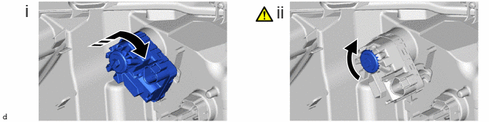
|
|
Turn |
|
Install in this Direction |
Install the headlight leveling motor as shown in the illustration.
Turn the aiming screw as shown in the illustration.
- NOTICE:
-
Turn the aiming screw the same number of times as they were turned during removal.
81144
12.INSTALL NO. 1 HEADLIGHT COVER
81134
13.INSTALL HEADLIGHT GASKET (w/ Adaptive High Beam System)
|
|
Click here()
|
81056A
14.INSTALL HEADLIGHT ECU SUB-ASSEMBLY (w/ Adaptive High Beam System)
|
|
Click here()
|