AUDIO / VIDEO RADIO ANTENNA CORD(for Roof) INSTALLATION
CAUTION / NOTICE / HINT
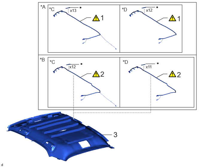
| Procedure | Part Name Code | 
|

|

|
|
|---|---|---|---|---|---|
| 1 | NO. 2 ANTENNA CORD SUB-ASSEMBLY | 86101J | ( ) |
- | - |
| 2 | NO. 2 ANTENNA CORD SUB-ASSEMBLY | 86101J | ()
|
- | - |
| 3 | ROOF HEADLINING ASSEMBLY | 63310 | - | - | - |
| *A | for Normal roof | *B | for Panoramic Moon Roof |
| *C | w/ Digital Audio Broadcasting Antenna | *D | w/o Digital Audio Broadcasting Antenna |
| ● | Non-reusable part | - | - |
PROCEDURE

 86101J
1.INSTALL NO. 2 ANTENNA CORD SUB-ASSEMBLY (for Normal Roof)
w/ Digital Audio Broadcasting Antenna:
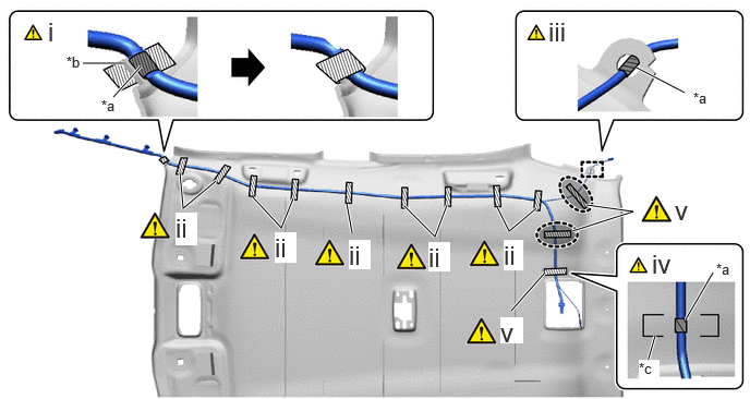
| *a | Marking Tape | *b | Protrusion |
| *c | Marking | - | - |

|
Adhesive Tape | 
|
Adjustment Area |
Align the marking tape on the No. 2 antenna cord sub-assembly with the protrusion on the front of the roof headlining assembly and wrap a new adhesive tape around the No. 2 antenna cord sub-assembly and protrusion of the roof headlining assembly.
Apply 9 new adhesive tapes to secure the No. 2 antenna cord sub-assembly as shown in the illustration.
Pass the marking tape on the No. 2 antenna cord sub-assembly through the cutout on the rear of the roof headlining assembly.
Align the marking tape on the No. 2 antenna cord sub-assembly with the marking of the roof headlining assembly.
Apply 3 new adhesive tapes to secure the No. 2 antenna cord sub-assembly as shown in the illustration.
- HINT:
-
Secure the extra length of the No. 2 antenna cord sub-assembly in the adjustment area as shown in the illustration.
w/o Digital Audio Broadcasting Antenna:
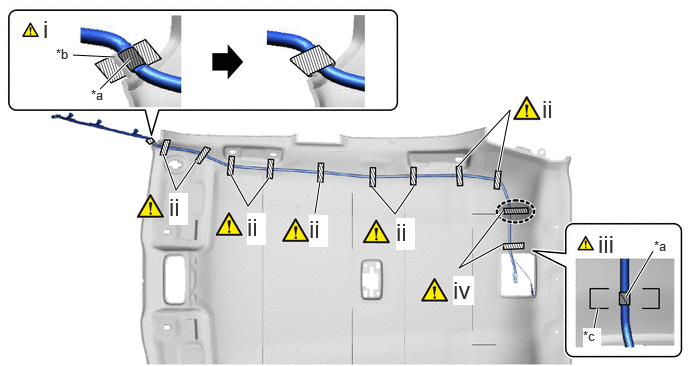
| *a | Marking Tape | *b | Protrusion |
| *c | Marking | - | - |
|
|
Adhesive Tape |
|
Adjustment Area |
Align the marking tape on the No. 2 antenna cord sub-assembly with the protrusion on the front of the roof headlining assembly and wrap a new adhesive tape around the No. 2 antenna cord sub-assembly and protrusion of the roof headlining assembly.
Apply 9 new adhesive tapes to secure the No. 2 antenna cord sub-assembly as shown in the illustration.
Align the marking tape on the No. 2 antenna cord sub-assembly with the marking of the roof headlining assembly.
Apply 2 new adhesive tapes to secure the No. 2 antenna cord sub-assembly as shown in the illustration.
- HINT:
-
Secure the extra length of the No. 2 antenna cord sub-assembly in the adjustment area as shown in the illustration.
86101J
2.INSTALL NO. 2 ANTENNA CORD SUB-ASSEMBLY (for Panoramic Moon Roof)
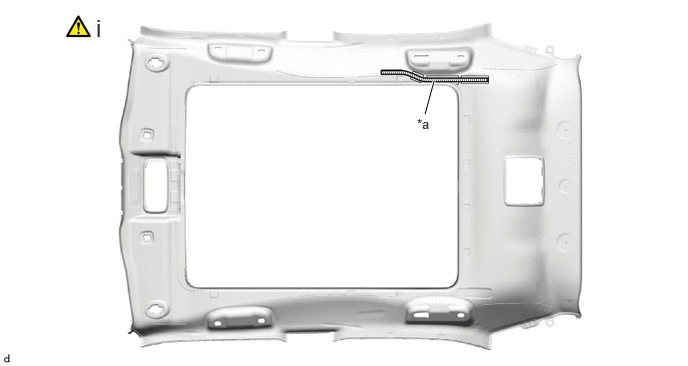
| *a | Marking | - | - |
|
|
Butyl Tape | - | - |
Apply a new butyl tape along the markings, while making sure that the butyl tape does not extend outside of the markings.
- NOTICE:
-
Apply the tape with even pressure, making sure that the tape does not extend outside of the markings of the roof headlining assembly.
w/ Digital Audio Broadcasting Antenna:
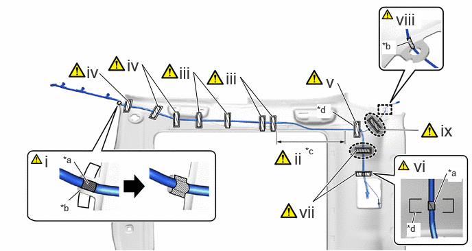
| *a | Marking Tape | *b | Protrusion |
| *c | Butyl Tape Area | *d | Marking |
|
|
Adhesive Tape |
|
Adjustment Area |
Align the marking tape on the No. 2 antenna cord sub-assembly with the protrusion on the front of the roof headlining assembly and wrap a new adhesive tape around the No. 2 antenna cord sub-assembly and protrusion of the roof headlining assembly.
Align the No. 2 antenna cord sub-assembly with the butyl tape area in the roof headlining assembly as shown in the illustration.
Apply 4 new adhesive tapes to secure the No. 2 antenna cord sub-assembly as shown in the illustration.
Apply 3 new adhesive tapes to secure the No. 2 antenna cord sub-assembly as shown in the illustration.
Align a new adhesive tape on the No. 2 antenna cord sub-assembly with the marking of the roof headlining assembly.
Align the marking tape on the No. 2 antenna cord sub-assembly with the marking of the roof headlining assembly.
Apply 2 new adhesive tapes to secure the No. 2 antenna cord sub-assembly as shown in the illustration.
- HINT:
-
Secure the extra length of the No. 2 antenna cord sub-assembly in the adjustment area as shown in the illustration.
Pass the marking tape on the No. 2 antenna cord sub-assembly through the cutout on the rear of the roof headlining assembly.
Apply a new adhesive tape to secure the No. 2 antenna cord sub-assembly as shown in the illustration.
- HINT:
-
Secure the extra length of the No. 2 antenna cord sub-assembly in the adjustment area as shown in the illustration.
w/o Digital Audio Broadcasting Antenna:
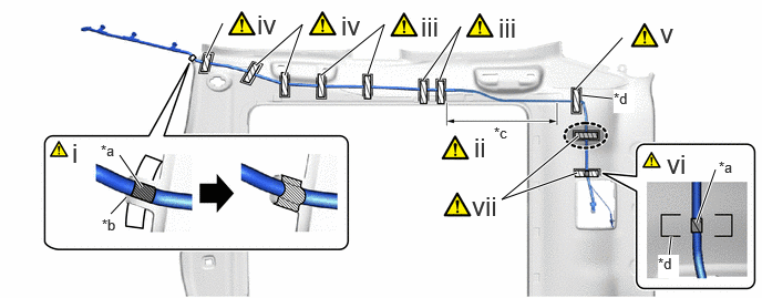
| *a | Marking Tape | *b | Protrusion |
| *c | Butyl Tape Area | *d | Marking |
|
|
Adhesive Tape |
|
Adjustment Area |
Align the marking tape on the No. 2 antenna cord sub-assembly with the protrusion on the front of the roof headlining assembly and wrap a new adhesive tape around the No. 2 antenna cord sub-assembly and protrusion of the roof headlining assembly.
Align the No. 2 antenna cord sub-assembly with the butyl tape area in the roof headlining assembly as shown in the illustration.
Apply 4 new adhesive tapes to secure the No. 2 antenna cord sub-assembly as shown in the illustration.
Apply 3 new adhesive tapes to secure the No. 2 antenna cord sub-assembly as shown in the illustration.
Align a new adhesive tape on the No. 2 antenna cord sub-assembly with the marking of the roof headlining assembly.
Align the marking tape on the No. 2 antenna cord sub-assembly with the marking of the roof headlining assembly.
Apply 2 new adhesive tapes to secure the No. 2 antenna cord sub-assembly as shown in the illustration.
- HINT:
-
Secure the extra length of the No. 2 antenna cord sub-assembly in the adjustment area as shown in the illustration.
63310
3.INSTALL ROOF HEADLINING ASSEMBLY