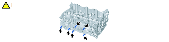
Home › Engine / Hybrid System › M15A-FKS (ENGINE MECHANICAL) › CYLINDER HEAD › from 2021.07
RM3700E _51 Engine / Hybrid System _093330 M15A-FKS ENGINE MECHANICAL _0440541 CYLINDER HEAD A

M15A-FKS ENGINE MECHANICAL  CYLINDER HEAD  DISASSEMBLY  


CAUTION / NOTICE / HINT
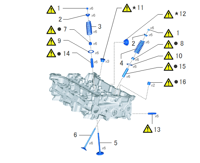
COMPONENTS (DISASSEMBLY)
A459763N01
3.573,5.104 3.99,5.104 false 2.833,4.833 3.25,4.833 false 5.448,4.094 5.448,4.427 false 5.396,2.948 5.813,2.948 false 4.521,2.635 5.656,2.406 5.656,2.406 5.823,2.406 false 4.74,2.313 5.667,2 5.667,2 5.833,2 false 4.802,2.104 5.667,1.583 5.667,1.583 5.833,1.583 false 4.333,2.094 4.333,1.927 4.333,1.927 4.844,1.75 false 4.75,1.417 4.75,1.333 4.75,1.333 5.198,1.229 false 5.354,1.063 5.667,1.167 5.667,1.167 5.833,1.167 false 4.542,1.385 5.656,0.51 5.656,0.51 5.823,0.51 false 3.688,2.104 4.188,0.281 4.188,0.281 4.354,0.281 false 3.271,0.948 3.438,0.948 false 2.25,0.292 3.083,0.292 false 2.49,1.052 2.656,1.052 2.656,1.052 3.208,1.521 false 2.271,1.438 2.438,1.438 2.438,1.438 3.177,1.854 false 2.583,1.885 2.75,1.885 2.75,1.885 3.24,2.229 false 2.26,0.688 2.427,0.688 2.427,0.688 3.063,0.531 false 2.021,0.156 2.302,0.51 0.281,0.354 18 false 1 6.292,1.042 6.573,1.396 0.281,0.354 18 false 1 4.698,1.417 4.979,1.771 0.281,0.354 18 false 2 2.073,0.552 2.354,0.906 0.281,0.354 18 false 2 3.49,0.813 3.771,1.167 0.281,0.354 18 false 3 4.271,2.125 4.552,2.479 0.281,0.354 18 false 4 4.063,4.979 4.344,5.333 0.281,0.354 18 false 5 2.615,4.688 2.896,5.042 0.281,0.354 18 false 6 2.25,0.906 2.531,1.26 0.281,0.354 18 false 7 6.438,1.417 6.719,1.771 0.281,0.354 18 false 8 2.042,1.323 2.323,1.677 0.281,0.354 18 false 9 6.26,1.865 6.781,2.229 0.521,0.365 18 false 10 4.885,0.135 5.396,0.49 0.51,0.354 18 false 11 6.396,0.354 6.917,0.729 0.521,0.375 18 false 12 5.479,4.5 5.99,4.844 0.51,0.344 18 false 13 2.229,1.781 2.646,2.135 0.417,0.354 18 false 14 6.385,2.24 6.823,2.604 0.438,0.365 18 false 15 6.396,2.792 6.917,3.146 0.521,0.354 18 false 16 6.25,2.865 6.531,3.219 0.281,0.354 10 false ● 5.417,2.979 5.813,3.344 0.396,0.365 10 false x2 6.229,2.313 6.51,2.667 0.281,0.354 10 false ● 2.052,1.865 2.333,2.219 0.281,0.354 10 false ● 2.063,0.979 2.344,1.333 0.281,0.354 10 false ● 6.26,0.417 6.542,0.771 0.281,0.354 10 false ★ 4.74,0.208 5.021,0.563 0.281,0.354 10 false ★ 6.24,1.49 6.521,1.844 0.281,0.354 10 false ● 5.385,0.927 5.781,1.292 0.396,0.365 10 false x6 5.333,1.177 5.729,1.542 0.396,0.365 10 false x6 5.219,1.438 5.615,1.802 0.396,0.365 10 false x6 4.844,2.063 5.24,2.427 0.396,0.365 10 false x6 4.76,2.313 5.156,2.677 0.396,0.365 10 false x6 4.531,2.667 4.927,3.031 0.396,0.365 10 false x6 3.365,2.146 3.76,2.51 0.396,0.365 10 false x6 3.406,1.823 3.802,2.188 0.396,0.365 10 false x6 3.344,1.49 3.74,1.854 0.396,0.365 10 false x6 3.344,1.063 3.74,1.427 0.396,0.365 10 false x6 3.281,0.479 3.677,0.844 0.396,0.365 10 false x6 3.208,0.229 3.604,0.594 0.396,0.365 10 false x6 3.656,5.229 4.052,5.594 0.396,0.365 10 false x6 3.198,5.052 3.594,5.417 0.396,0.365 10 false x6 5.552,4.083 5.948,4.448 0.396,0.365 10 false x6 3.781,2.125 4.177,2.49 0.396,0.365 10 false x3

Procedure Part Name Code
Z101186

Z101188

Z101187

1 VALVE SPRING RETAINER LOCK 13741A (Click here) - -
2 VALVE SPRING RETAINER - - - -
3 INTAKE VALVE COMPRESSION SPRING 13711M - - -
4 EXHAUST VALVE COMPRESSION SPRING 13715H - - -
5 INTAKE VALVE 13711 - - -
6 EXHAUST VALVE 13715 - - -
7 INTAKE VALVE STEM OIL SEAL 13711E (Click here) - -
8 EXHAUST VALVE STEM OIL SEAL 13715A (Click here) - -
9 INTAKE VALVE SPRING SEAT 13734A (Click here) - -
10 EXHAUST VALVE SPRING SEAT 13734B (Click here) - -
11 NO. 1 STRAIGHT SCREW PLUG 11117E (Click here) - -
12 NO. 2 STRAIGHT SCREW PLUG 11117F (Click here) - -
13 STUD BOLT - (Click here) - -
14 INTAKE VALVE GUIDE BUSH 11122 (Click here) - -
15 EXHAUST VALVE GUIDE BUSH 11126 (Click here) - -
16 RING PIN 11115A (Click here) - -

● Non-reusable part ★ Precoated part

CAUTION / NOTICE / HINT

The necessary procedures (adjustment, calibration, initialization, or registration) that must be performed after parts are removed and installed, or replaced during cylinder head removal/installation are shown below.

Necessary Procedure After Parts Removed/Installed/Replaced
Replaced Part or Performed Procedure Necessary Procedure Effect/Inoperative Function when Necessary Procedure not Performed Link
Reconnected to auxiliary battery terminal Memorize steering angle neutral point Parking assist monitor system (Click here)
Panoramic view monitor system (w/o Advanced Park) (Click here)
Cylinder head sub-assembly Inspection after repair
·

Poor idle, etc.

·

Engine start function, etc.


(Click here)

PROCEDURE

Hide 13741A 1.REMOVE VALVE SPRING RETAINER LOCK
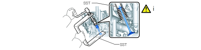
a.
A460688N01
3.521,1.365 4.083,1.583 4.083,1.583 4.25,1.583 false 3.271,0.104 3.438,0.104 3.438,0.104 4.135,0.229 true 4.281,1.531 4.74,1.729 0.458,0.198 10 false SST 2.979,0.042 3.438,0.24 0.458,0.198 10 false SST 5.427,0.167 5.885,0.49 0.458,0.323 18 false i

i.

Using SST, compress each compression spring and remove the 12 valve spring retainer locks.

SST
09202-70020  (09202-01010, 09202-01020)
09202-00021  


Hide 2.REMOVE VALVE SPRING RETAINER

a.
A461723


Hide 13711M 3.REMOVE INTAKE VALVE COMPRESSION SPRING
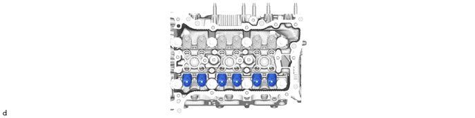
a.
A461725


Hide 13715H 4.REMOVE EXHAUST VALVE COMPRESSION SPRING

a.

Remove using the same procedure as for the intake valve compression spring.


Hide 13711 5.REMOVE INTAKE VALVE

a.
A461727


Hide 13715 6.REMOVE EXHAUST VALVE

a.

Remove using the same procedure as for the intake valve.


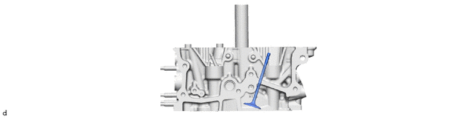
Hide 13711E 7.REMOVE INTAKE VALVE STEM OIL SEAL
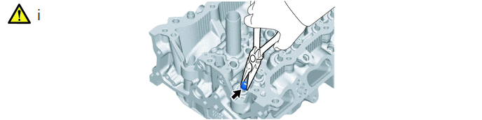
a.
A460689N01
0.531,0.083 0.813,0.438 0.281,0.354 18 false i


Hide 13715A 8.REMOVE EXHAUST VALVE STEM OIL SEAL

a.

Remove using the same procedure as for the intake valve stem oil seal.


Hide 13734A 9.REMOVE INTAKE VALVE SPRING SEAT
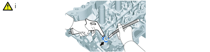
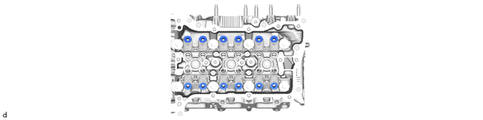
a.
A460690N01
0.479,0.063 0.76,0.417 0.281,0.354 18 false i

i.

Using compressed air and a Magnet Hand, remove the 6 valve spring seats from the cylinder head sub-assembly by blowing air onto them.


Hide 13734B 10.REMOVE EXHAUST VALVE SPRING SEAT

a.

Remove using the same procedure as for the intake valve spring seat.


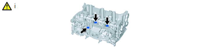
Hide 11117E 11.REMOVE NO. 1 STRAIGHT SCREW PLUG

Z101186

NOTICE:

If coolant leaks from a No. 1 straight screw plug or a plug is corroded, replace it.


a.
A461374N01
0.49,0.073 0.771,0.427 0.281,0.354 18 false i

i.

Using a 6 mm straight hexagon wrench, remove the 3 No. 1 straight screw plugs from the cylinder head sub-assembly.


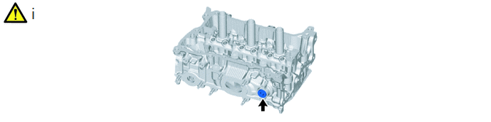
Hide 11117F 12.REMOVE NO. 2 STRAIGHT SCREW PLUG

Z101186

NOTICE:

If coolant leaks from a No. 2 straight screw plug or a plug is corroded, replace it.


a.
A460691N01
0.438,0.063 0.719,0.417 0.281,0.354 18 false i

i.

Using a 10 mm straight hexagon wrench, remove the No. 2 straight screw plug from the cylinder head sub-assembly.


Hide 13.REMOVE STUD BOLT

Z101186

NOTICE:

If a stud bolt is deformed or its threads are damaged, replace it.


a.
A460692N01
0.458,0.083 0.74,0.438 0.281,0.354 18 false i

i.

Using an E8 "TORX" socket wrench, remove the 6 stud bolts.


Hide 11122 14.REMOVE INTAKE VALVE GUIDE BUSH
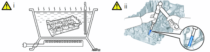
a.
A460693N01
0.427,0.042 0.708,0.396 0.281,0.354 18 false i 4.219,0.073 4.5,0.427 0.281,0.354 18 false ii

i.

Heat the cylinder head sub-assembly to between 80 and 100°C (176 to 212°F).

CAUTION:

Be sure to wear protective gloves.


ii.

Using SST and a hammer, tap out the intake valve guide bush.

SST
09201-01055  
09950-70010  (09951-07100)


Hide 11126 15.REMOVE EXHAUST VALVE GUIDE BUSH
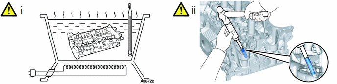
a.
A460694N01
0.406,0.083 0.688,0.438 0.281,0.354 18 false i 4.042,0.073 4.323,0.427 0.281,0.354 18 false ii

i.

Heat the cylinder head sub-assembly to between 80 and 100°C (176 to 212°F).

CAUTION:

Be sure to wear protective gloves.


ii.

Using SST and a hammer, tap out the exhaust valve guide bush.

SST
09201-01055  
09950-70010  (09951-07100)


Hide 11115A 16.REMOVE RING PIN

Z101186

NOTICE:

It is not necessary to remove the ring pins unless they are being replaced.


a.
A460695