AUDIO / VIDEO AUDIO AND VISUAL SYSTEM(for Radio and Display Type with TAS Type) GPS Antenna Malfunction
WIRING DIAGRAM
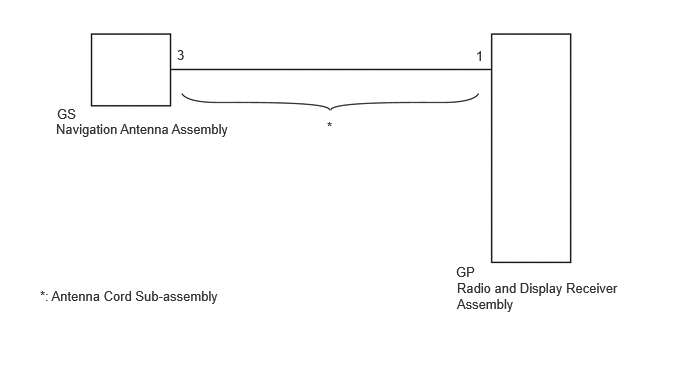
CAUTION / NOTICE / HINT
- NOTICE:
-
Check that the antenna cord sub-assembly cable is properly installed and does not have any sharp bends, pinching or loose connections before performing following procedure.
-
Click hereGeneral>INTRODUCTION>HOW TO TROUBLESHOOT ECU CONTROLLED SYSTEMS>HOW TO PROCEED WITH TROUBLESHOOTING
PROCEDURE
Clear the fault list.
- Result:
Proceed to NEXT
NEXT
Check for color of status indicators.
- Result:
Result Proceed to GPS antenna indicator is red A GPS antenna indicator is green or gray B
A
B
Click hereGeneral>INTRODUCTION>HOW TO TROUBLESHOOT ECU CONTROLLED SYSTEMS>HOW TO PROCEED WITH TROUBLESHOOTING
Remove the antenna cord sub-assembly.
Click hereAudio / Visual / Telematics>AUDIO / VIDEO>RADIO ANTENNA CORD (for Roof)>REMOVAL
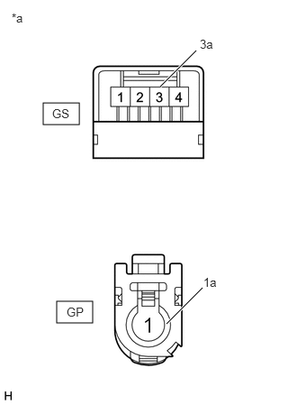
| *a | Component without harness connected
(Antenna Cord Sub-assembly) |
Measure the resistance according to the value(s) in the table below.
- Standard Resistance:
Tester Connection Condition Specified Condition GS-3 - GP-1 Always Below 1 Ω GS-3a - GP-1a Always Below 1 Ω GS-3 or GP-1 - Body ground Always 10 kΩ or higher
- Result:
Proceed to OK NG
OK
NG
Remove the navigation antenna assembly.
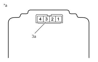
| *a | Component without harness connected
(Navigation Antenna Assembly) |
Measure the resistance according to the value(s) in the table below.
- Standard Resistance:
Tester Connection Condition Specified Condition 3 - 3a Always 50 to 500 Ω
- Result:
Proceed to OK NG
OK
NG