PARK ASSIST / MONITORING PANORAMIC VIEW MONITOR SYSTEM(w/ Advanced Park) Infrared light does not Turn ON at Low Illumination Time
DESCRIPTION
The parking assist ECU illuminates the parking assist light at night or other times when the light level is low to enable image recognition.
WIRING DIAGRAM
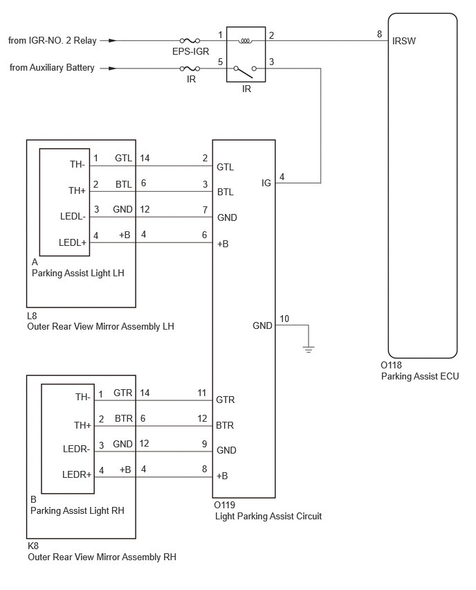
CAUTION / NOTICE / HINT
- NOTICE:
- ·
Depending on the parts that are replaced or operations that are performed during vehicle inspection or maintenance, calibration of other systems as well as the panoramic view monitor system may be needed.
·Inspect the fuse for circuits related to this system before performing the following procedure.
PROCEDURE
Disconnect the light parking assist circuit connector.
Enter the following menus: Body Electrical / Clearance Warning / Utility.
- Chassis > Circumference Monitoring Camera Control Module > Utility
-
Tester Display IR Projector Inspection - 50005 470 4641
Measure the resistance according to the value(s) in the table below.
- Standard Resistance:
Tester Connection Condition Specified Condition Click Location & Routing(O119)Location & Routingewd_type=routing;type=c;code=O119
Click Connector(O119)Body>Floor Wire>Light Parking Assist Circuitewd_type=component;type=c;code=O119;pinno=10
O119-10 (GND) - Body ground Always Below 1 Ω
Measure the voltage according to the value(s) in the table below.
- Standard Voltage:
Tester Connection Switch Condition Specified Condition Click Location & Routing(O119)Location & Routingewd_type=routing;type=c;code=O119
Click Connector(O119)Body>Floor Wire>Light Parking Assist Circuitewd_type=component;type=c;code=O119;pinno=4
O119-4 (IG) - Body ground IR Emitter Illumination Trigger OFF Below 1 V O119-4 (IG) - Body ground IR Emitter Illumination Trigger ON 11 to 14 V
- Result:
Proceed to OK NG
OK
NG
Enter the following menus: Chassis / Clearance Warning / Utility.
- Chassis > Circumference Monitoring Camera Control Module > Utility
-
Tester Display IR Projector Inspection - 50005 470 4641
Cover the bottom of the outer rear view mirror assembly with your hand or a cloth.
According to the display on the GTS, illuminate the parking assist light and check for changes in the radio and display receiver assembly screen display.
- HINT:
- ·
When the parking assist light illuminates, the radio and display receiver assembly screen display will appear to be illuminated by a purplish light.
·It is necessary to turn the ignition switch off once to illuminate the parking assist light again.
- Result:
Result Proceed to All parking assist lights do not illuminate A Parking assist light on the left side only does not illuminate B Parking assist light on the right side only does not illuminate C All illuminate D
A
B
C
D
Click hereGeneral>INTRODUCTION>HOW TO TROUBLESHOOT ECU CONTROLLED SYSTEMS>HOW TO PROCEED WITH TROUBLESHOOTING
Disconnect the O119 light parking assist circuit connector.
Disconnect the L8 outer rear view mirror assembly LH connector.
Measure the resistance according to the value(s) in the table below.
- Standard Resistance:
Tester Connection Condition Specified Condition Click Location & Routing(O119,L8)Location & Routingewd_type=routing;type=c,c;code=O119,L8
Click Connector(O119)Body>Floor Wire>Light Parking Assist Circuitewd_type=component;type=c;code=O119;pinno=2,3,6,7
Click Connector(L8)Body>Front Door Wire LH / Television Camera Wire>Outer Rear View Mirror Assembly LHewd_type=component;type=c;code=L8;pinno=14,6,4,12
O119-2 (GTL) - L8-14 (GTL) Always Below 1 Ω O119-3 (BTL) - L8-6 (BTL) Always Below 1 Ω O119-6 (+B) - L8-4 (+B) Always Below 1 Ω O119-7 (GND) - L8-12 (GND) Always Below 1 Ω O119-2 (GTL) or L8-14 (GTL) - Body ground Always 10 kΩ or higher O119-3 (BTL) or L8-6 (BTL) - Body ground Always 10 kΩ or higher O119-6 (+B) or L8-4 (+B) - Body ground Always 10 kΩ or higher O119-7 (GND) or L8-12 (GND) - Body ground Always 10 kΩ or higher
- Result:
Proceed to OK NG
OK
NG
Disconnect the A parking assist light LH connector.
Disconnect the L8 outer rear view mirror assembly LH connector.
Measure the resistance according to the value(s) in the table below.
- Standard Resistance:
Tester Connection Condition Specified Condition Click Location & Routing(L8)Location & Routingewd_type=routing;type=c;code=L8
Click Connector(L8)Body>Front Door Wire LH / Television Camera Wire>Outer Rear View Mirror Assembly LHewd_type=component;type=c;code=L8;pinno=14,6,12,4
A-1 (TH-) - L8-14 (GTL) Always Below 1 Ω A-2 (TH+) - L8-6 (BTL) Always Below 1 Ω A-3 (LEDL-) - L8-12 (GND) Always Below 1 Ω A-4 (LEDL+) - L8-4 (+B) Always Below 1 Ω A-1 (TH-) or L8-14 (GTL) - Body ground Always 10 kΩ or higher A-2 (TH+) or L8-6 (BTL) - Body ground Always 10 kΩ or higher A-3 (LEDL-) or L8-12 (GND) - Body ground Always 10 kΩ or higher A-4 (LEDL+) or L8-4 (+B) - Body ground Always 10 kΩ or higher
- Result:
Proceed to OK NG
OK
NG
Disconnect the O119 light parking assist circuit connector.
Disconnect the K8 outer rear view mirror assembly RH connector.
Measure the resistance according to the value(s) in the table below.
- Standard Resistance:
Tester Connection Condition Specified Condition Click Location & Routing(O119,K8)Location & Routingewd_type=routing;type=c,c;code=O119,K8
Click Connector(O119)Body>Floor Wire>Light Parking Assist Circuitewd_type=component;type=c;code=O119;pinno=11,12,8,9
Click Connector(K8)Body>Front Door Wire RH / Television Camera Wire>Outer Rear View Mirror Assembly RHewd_type=component;type=c;code=K8;pinno=14,6,4,12
O119-11 (GTR) - K8-14 (GTR) Always Below 1 Ω O119-12 (BTR) - K8-6 (BTR) Always Below 1 Ω O119-8 (+B) - K8-4 (+B) Always Below 1 Ω O119-9 (GND) - K8-12 (GND) Always Below 1 Ω O119-11 (GTR) or K8-14 (GTR) - Body ground Always 10 kΩ or higher O119-12 (BTR) or K8-6 (BTR) - Body ground Always 10 kΩ or higher O119-8 (+B) or K8-4 (+B) - Body ground Always 10 kΩ or higher O119-9 (GND) or K8-12 (GND) - Body ground Always 10 kΩ or higher
- Result:
Proceed to OK NG
OK
NG
Disconnect the B parking assist light RH connector.
Disconnect the K8 outer rear view mirror assembly RH connector.
Measure the resistance according to the value(s) in the table below.
- Standard Resistance:
Tester Connection Condition Specified Condition Click Location & Routing(K8)Location & Routingewd_type=routing;type=c;code=K8
Click Connector(K8)Body>Front Door Wire RH / Television Camera Wire>Outer Rear View Mirror Assembly RHewd_type=component;type=c;code=K8;pinno=14,6,12,4
B-1 (TH-) - K8-14 (GTR) Always Below 1 Ω B-2 (TH+) - K8-6 (BTR) Always Below 1 Ω B-3 (LEDR-) - K8-12 (GND) Always Below 1 Ω B-4 (LEDR+) - K8-4 (+B) Always Below 1 Ω B-1 (TH-) or K8-14 (GTR) - Body ground Always 10 kΩ or higher B-2 (TH+) or K8-6 (BTR) - Body ground Always 10 kΩ or higher B-3 (LEDR-) or K8-12 (GND) - Body ground Always 10 kΩ or higher B-4 (LEDR+) or K8-4 (+B) - Body ground Always 10 kΩ or higher
- Result:
Proceed to OK NG
OK
NG
Disconnect the L8 outer rear view mirror assembly LH connector.
Enter the following menus: Body Electrical / Clearance Warning / Utility.
- Chassis > Circumference Monitoring Camera Control Module > Utility
-
Tester Display IR Projector Inspection - 50005 470 4641
Measure the voltage according to the value(s) in the table below.
- Standard Voltage:
Tester Connection Switch Condition Specified Condition Click Location & Routing(L8)Location & Routingewd_type=routing;type=c;code=L8
Click Connector(L8)Body>Front Door Wire LH / Television Camera Wire>Outer Rear View Mirror Assembly LHewd_type=component;type=c;code=L8;pinno=4
L8-4 (+B) - Body ground IR Emitter Illumination Trigger OFF Below 1 V L8-4 (+B) - Body ground IR Emitter Illumination Trigger ON 41 to 48 V
- Result:
Proceed to OK NG
OK
NG
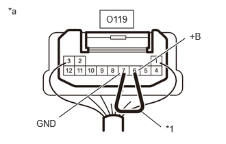
| *1 | Service Wire |
| *a | Rear view of wire harness connector
(to Light Parking Assist Circuit) |
Using a service wire, connect terminals 6 (+B) and 7 (GND) of light parking assist circuit connector.
- NOTICE:
-
Do not forcibly insert the service wire into the terminals of the connector when connecting a service wire.
Cover the bottom of the outer rear view mirror assembly with your hand or a cloth.
According to the display on the GTS, illuminate the parking assist light and check for changes in the multi-display screen display.
- HINT:
- ·
When the parking assist light illuminates, the radio and display receiver assembly screen display will appear to be illuminated by a purplish light.
·It is necessary to turn the ignition switch off once to illuminate the parking assist light again.
- Result:
Result Proceed to Parking assist light RH illuminate A Parking assist light RH not illuminate B
A
B
Disconnect the O119 light parking assist circuit connector.
Disconnect the L8 outer rear view mirror assembly LH connector.
Measure the resistance according to the value(s) in the table below.
- Standard Resistance:
Tester Connection Condition Specified Condition Click Location & Routing(O119,L8)Location & Routingewd_type=routing;type=c,c;code=O119,L8
Click Connector(O119)Body>Floor Wire>Light Parking Assist Circuitewd_type=component;type=c;code=O119;pinno=2,3,6,7
Click Connector(L8)Body>Front Door Wire LH / Television Camera Wire>Outer Rear View Mirror Assembly LHewd_type=component;type=c;code=L8;pinno=14,6,4,12
O119-2 (GTL) - L8-14 (GTL) Always Below 1 Ω O119-3 (BTL) - L8-6 (BTL) Always Below 1 Ω O119-6 (+B) - L8-4 (+B) Always Below 1 Ω O119-7 (GND) - L8-12 (GND) Always Below 1 Ω O119-2 (GTL) or L8-14 (GTL) - Body ground Always 10 kΩ or higher O119-3 (BTL) or L8-6 (BTL) - Body ground Always 10 kΩ or higher O119-6 (+B) or L8-4 (+B) - Body ground Always 10 kΩ or higher O119-7 (GND) or L8-12 (GND) - Body ground Always 10 kΩ or higher
- Result:
Proceed to OK NG
OK
NG
Disconnect the A parking assist light LH connector.
Disconnect the L8 outer rear view mirror assembly LH connector.
Measure the resistance according to the value(s) in the table below.
- Standard Resistance:
Tester Connection Condition Specified Condition Click Location & Routing(L8)Location & Routingewd_type=routing;type=c;code=L8
Click Connector(L8)Body>Front Door Wire LH / Television Camera Wire>Outer Rear View Mirror Assembly LHewd_type=component;type=c;code=L8;pinno=14,6,12,4
A-1 (TH-) - L8-14 (GTL) Always Below 1 Ω A-2 (TH+) - L8-6 (BTL) Always Below 1 Ω A-3 (LEDL-) - L8-12 (GND) Always Below 1 Ω A-4 (LEDL+) - L8-4 (+B) Always Below 1 Ω A-1 (TH-) or L8-14 (GTL) - Body ground Always 10 kΩ or higher A-2 (TH+) or L8-6 (BTL) - Body ground Always 10 kΩ or higher A-3 (LEDL-) or L8-12 (GND) - Body ground Always 10 kΩ or higher A-4 (LEDL+) or L8-4 (+B) - Body ground Always 10 kΩ or higher
- Result:
Proceed to OK NG
OK
NG
Replace the parking assist light LH with a known good one.
Click hereADAS / AD>ADVANCED PARK>PARKING ASSIST LIGHT>REMOVAL
- Result:
Proceed to NEXT
NEXT
Enter the following menus: Chassis / Clearance Warning / Utility.
- Chassis > Circumference Monitoring Camera Control Module > Utility
-
Tester Display IR Projector Inspection - 50005 470 4641
Cover the bottom of the outer rear view mirror assembly with your hand or a cloth.
According to the display on the GTS, illuminate the parking assist light and check for changes in the radio and display receiver assembly screen display.
- HINT:
- ·
When the parking assist light illuminates, the radio and display receiver assembly screen display will appear to be illuminated by a purplish light.
·It is necessary to turn the ignition switch off once to illuminate the parking assist light again.
- Result:
Result Proceed to Parking assist lights illuminate A Parking assist lights not illuminate B
A
B
Disconnect the O119 light parking assist circuit connector.
Disconnect the K8 outer rear view mirror assembly RH connector.
Measure the resistance according to the value(s) in the table below.
- Standard Resistance:
Tester Connection Condition Specified Condition Click Location & Routing(O119,K8)Location & Routingewd_type=routing;type=c,c;code=O119,K8
Click Connector(O119)Body>Floor Wire>Light Parking Assist Circuitewd_type=component;type=c;code=O119;pinno=11,12,8,9
Click Connector(K8)Body>Front Door Wire RH / Television Camera Wire>Outer Rear View Mirror Assembly RHewd_type=component;type=c;code=K8;pinno=14,6,4,12
O119-11 (GTR) - K8-14 (GTR) Always Below 1 Ω O119-12 (BTR) - K8-6 (BTR) Always Below 1 Ω O119-8 (+B) - K8-4 (+B) Always Below 1 Ω O119-9 (GND) - K8-12 (GND) Always Below 1 Ω O119-11 (GTR) or K8-14 (GTR) - Body ground Always 10 kΩ or higher O119-12 (BTR) or K8-6 (BTR) - Body ground Always 10 kΩ or higher O119-8 (+B) or K8-4 (+B) - Body ground Always 10 kΩ or higher O119-9 (GND) or K8-12 (GND) - Body ground Always 10 kΩ or higher
- Result:
Proceed to OK NG
OK
NG
Disconnect the B parking assist light RH connector.
Disconnect the K8 outer rear view mirror assembly RH connector.
Measure the resistance according to the value(s) in the table below.
- Standard Resistance:
Tester Connection Condition Specified Condition Click Location & Routing(K8)Location & Routingewd_type=routing;type=c;code=K8
Click Connector(K8)Body>Front Door Wire RH / Television Camera Wire>Outer Rear View Mirror Assembly RHewd_type=component;type=c;code=K8;pinno=14,6,12,4
B-1 (TH-) - K8-14 (GTR) Always Below 1 Ω B-2 (TH+) - K8-6 (BTR) Always Below 1 Ω B-3 (LEDR-) - K8-12 (GND) Always Below 1 Ω B-4 (LEDR+) - K8-4 (+B) Always Below 1 Ω B-1 (TH-) or K8-14 (GTR) - Body ground Always 10 kΩ or higher B-2 (TH+) or K8-6 (BTR) - Body ground Always 10 kΩ or higher B-3 (LEDR-) or K8-12 (GND) - Body ground Always 10 kΩ or higher B-4 (LEDR+) or K8-4 (+B) - Body ground Always 10 kΩ or higher
- Result:
Proceed to OK NG
OK
NG
Replace the parking assist light RH with a known good one.
Click hereADAS / AD>ADVANCED PARK>PARKING ASSIST LIGHT>REMOVAL
- Result:
Proceed to NEXT
NEXT
Enter the following menus: Chassis / Clearance Warning / Utility.
- Chassis > Circumference Monitoring Camera Control Module > Utility
-
Tester Display IR Projector Inspection - 50005 470 4641
Cover the bottom of the outer rear view mirror assembly with your hand or a cloth.
According to the display on the GTS, illuminate the parking assist light and check for changes in the radio and display receiver assembly screen display.
- HINT:
- ·
When the parking assist light illuminates, the radio and display receiver assembly screen display will appear to be illuminated by a purplish light.
·It is necessary to turn the ignition switch off once to illuminate the parking assist light again.
- Result:
Result Proceed to Parking assist lights illuminate A Parking assist lights not illuminate B
A
B
OK
NG
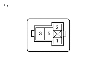
| *a | Front view of wire harness connector
(IR Relay) |
Remove the IR relay from No. 3 engine room relay block.
Measure the voltage according to the value(s) in the table below.
- Standard Voltage:
Tester Connection Switch Condition Specified Condition IR relay terminal 1 - Body ground Ignition Switch ON 11 to 14 V Ignition Switch off Below 1V IR relay terminal 5 - Body ground Ignition Switch ON 11 to 14 V Ignition Switch off Below 1V
- Result:
Proceed to OK NG
OK
NG
Remove the IR relay from No. 3 engine room relay block.
Disconnect the O118 parking assist ECU connector.
Disconnect the O119 light parking assist circuit connector.
Measure the resistance according to the value(s) in the table below.
- Standard Resistance:
Tester Connection Condition Specified Condition Click Location & Routing(O118,O119)Location & Routingewd_type=routing;type=c,c;code=O118,O119
Click Connector(O118)Body>Floor Wire>Parking Assist ECUewd_type=component;type=c;code=O118;pinno=8
Click Connector(O119)Body>Floor Wire>Light Parking Assist Circuitewd_type=component;type=c;code=O119;pinno=4
IR relay terminal 2 - O118-8 (IRSW) Always Below 1 Ω IR relay terminal 3 - O119-4 (IG) Always Below 1 Ω
- Result:
Proceed to OK NG
OK
NG
Replace the parking assist circuit with a known good one.
Click hereADAS / AD>ADVANCED PARK>PARKING ASSIST LIGHT CONTROL RELAY>REMOVAL
- Result:
Proceed to NEXT
NEXT
Enter the following menus: Chassis / Clearance Warning / Utility.
- Chassis > Circumference Monitoring Camera Control Module > Utility
-
Tester Display IR Projector Inspection - 50005 470 4641
Cover the bottom of the outer rear view mirror assembly with your hand or a cloth.
According to the display on the GTS, illuminate the parking assist light and check for changes in the radio and display receiver assembly screen display.
- HINT:
- ·
When the parking assist light illuminates, the radio and display receiver assembly screen display will appear to be illuminated by a purplish light.
·It is necessary to turn the ignition switch off once to illuminate the parking assist light again.
- Result:
Result Proceed to Parking assist lights illuminate A Parking assist lights not illuminate B
A
B