ACOUSTIC VEHICLE ALERTING SYSTEM ACOUSTIC VEHICLE ALERTING SYSTEM There is No Sound Made
DESCRIPTION
Based on signals received from each ECU, the vehicle approaching speaker controller outputs warning sounds through the vehicle approaching speaker assembly.
WIRING DIAGRAM
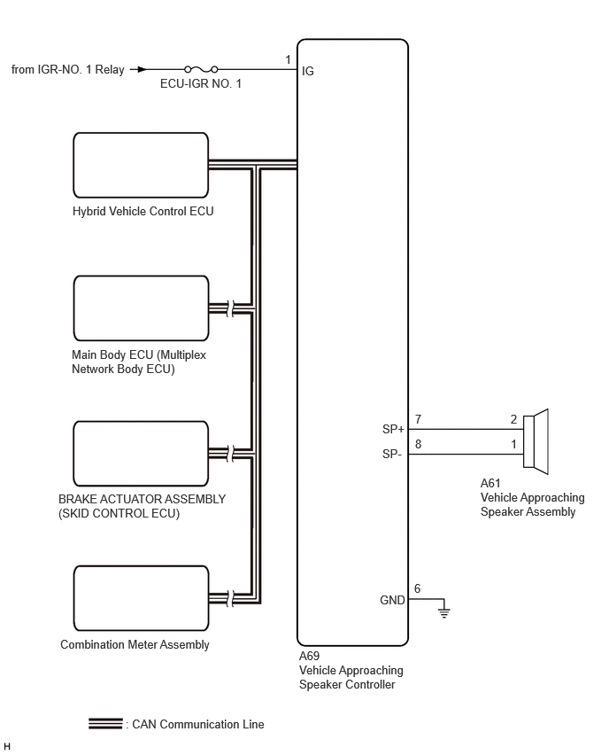
CAUTION / NOTICE / HINT
- NOTICE:
- ·
Inspect the fuses for circuits related to this system before performing the following procedure.
·The acoustic vehicle alerting system uses the CAN communication system. Inspect the communication functions by following How to Proceed with Troubleshooting.
PROCEDURE
Check for DTCs.
- Body Electrical > Vehicle Proximity Notification System > Trouble Codes
- 50001 458
- Result:
Result Proceed to B135013 and B135019 are not output A B135013 or B135019 is output B
A
B
Click hereVehicle Exterior>ACOUSTIC VEHICLE ALERTING SYSTEM>ACOUSTIC VEHICLE ALERTING SYSTEM>B135013
Perform the Active Test according to the display on the GTS.
- Body Electrical > Vehicle Proximity Notification System > Active Test
-
Tester Display Measurement Item Control Range Diagnostic Note Proximity Sound (Vehicle Stationary) 0 km/h (0 mph) vehicle proximity warning sound OFF or ON -
- Body Electrical > Vehicle Proximity Notification System > Active Test
-
Tester Display Proximity Sound (Vehicle Stationary) - 50004 458 42001
- Result:
Result Proceed to The warning sound is produced A The warning sound is not produced B
A
B
Disconnect the A69 vehicle approaching speaker controller connector.
Measure the voltage according to the value(s) in the table below.
- Standard Voltage:
Tester Connection Switch Condition Specified Condition Click Location & Routing(A69)Location & Routingewd_type=routing;type=c;code=A69
Click Connector(A69)Instrument Panel>Engine Room Main Wire>Vehicle Approaching Speaker Controllerewd_type=component;type=c;code=A69;pinno=1
A69-1 (IG) - Body ground Ignition switch ON 11 to 14 V
Measure the resistance according to the value(s) in the table below.
- Standard Resistance:
Tester Connection Condition Specified Condition Click Location & Routing(A69)Location & Routingewd_type=routing;type=c;code=A69
Click Connector(A69)Instrument Panel>Engine Room Main Wire>Vehicle Approaching Speaker Controllerewd_type=component;type=c;code=A69;pinno=6
A69-6 (GND) - Body ground Always Below 1 Ω
- Result:
Proceed to OK NG
OK
NG