Home › Engine / Hybrid System › M15A-FXE (ENGINE MECHANICAL) › CYLINDER BLOCK › from 2021.07
RM3700E _51 Engine / Hybrid System _093331 M15A-FXE ENGINE MECHANICAL _0440551 CYLINDER BLOCK A

M15A-FXE ENGINE MECHANICAL  CYLINDER BLOCK  DISASSEMBLY  


CAUTION / NOTICE / HINT
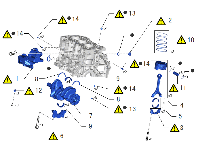
COMPONENTS (DISASSEMBLY)
A476410N01
5.583,1.104 6.115,1.917 0.531,0.813 5.427,2.177 6.052,3.542 0.625,1.365 5.427,3.542 5.813,3.927 0.385,0.385 4.427,2.469 4.542,2.281 4.542,2.281 4.708,2.281 false 3.667,1.01 3.948,0.49 3.948,0.49 4.115,0.49 false 3.344,3.573 3.958,3.938 3.958,3.938 4.125,3.938 false 0.865,1.208 1.031,1.208 1.031,1.208 1.51,1.729 false 1.365,1.323 1.885,0.698 1.885,0.698 2.052,0.698 false 3.438,3.104 3.938,3.219 3.938,3.219 4.104,3.219 false 0.583,3.281 0.865,3.281 false 6.417,3.042 6.417,2.74 false 6.125,1.406 6.406,1.406 false 2.302,3.833 2.948,4.573 2.948,4.573 3.115,4.573 false 2.594,2.865 4.104,2.865 false 2.896,3.073 3.938,3.594 3.938,3.594 4.104,3.594 false 1.417,2.844 1.583,2.844 1.583,2.844 2.146,2.677 false 2.052,4.792 2.052,4.24 false 2.677,3.802 2.969,4.198 2.969,4.198 3.135,4.198 false 5.813,3.813 6.208,4.219 6.208,4.219 6.375,4.219 false 5.938,3.542 6.24,3.813 6.24,3.813 6.406,3.813 false 5.698,4.104 5.948,4.604 5.948,4.604 6.115,4.604 false 4.698,1.896 5.49,0.75 5.49,0.75 5.656,0.75 false 4.292,1.906 4.479,1.292 4.479,1.292 4.646,1.292 false 1.771,2.365 1.771,2.208 false 0.708,2.854 0.875,2.854 0.875,2.854 1.146,2.49 false 6.625,2.75 6.677,2.583 6.677,2.583 6.844,2.583 false 6.146,2.479 6.198,2.313 6.198,2.313 6.365,2.313 false 0.531,2.719 0.813,3.073 0.281,0.354 18 false 1 6.073,0.594 6.354,0.948 0.281,0.354 18 false 2 1.458,1.26 1.771,1.458 0.313,0.198 10 false x2 3.75,0.979 4.063,1.177 0.313,0.198 10 false x2 3.385,3.458 3.698,3.656 0.313,0.198 10 false x8 4.458,2.531 4.771,2.729 0.313,0.198 10 false x2 3.417,3.146 3.729,3.344 0.313,0.198 10 false x2 0.542,3.74 0.854,3.938 0.313,0.198 10 false x3 0.573,3.323 0.885,3.521 0.313,0.198 10 false x3 6.49,4.49 6.771,4.844 0.281,0.354 18 false 3 6.5,3.677 6.781,4.031 0.281,0.354 18 false 4 6.479,2.563 6.792,2.76 0.313,0.198 10 false x3 6.208,2.427 6.521,2.625 0.313,0.198 10 false x3 6.667,2.719 6.979,2.917 0.313,0.198 10 false x3 6.438,4.073 6.719,4.427 0.281,0.354 18 false 5 6.177,1.802 6.594,2.021 0.417,0.219 10 false x3 2.365,3.729 2.677,3.927 0.313,0.198 10 false x4 3.198,4.052 3.479,4.406 0.281,0.354 18 false 7 2.406,2.885 2.719,3.083 0.313,0.198 10 false x4 4.198,3.458 4.479,3.813 0.281,0.354 18 false 8 1.24,2.729 1.521,3.083 0.281,0.354 18 false 8 2.156,4.792 2.438,5.146 0.281,0.354 18 false 6 3.188,4.438 3.469,4.792 0.281,0.354 18 false 9 2.344,4.177 2.656,4.375 0.313,0.198 10 false x4 1.417,4.458 1.729,4.656 0.313,0.198 10 false x8 6.76,1.313 7.156,1.656 0.396,0.344 18 false 10 6.479,3.042 6.969,3.406 0.49,0.365 18 false 11 1.25,3.135 1.781,3.417 0.531,0.281 18 false 12 4.646,3.813 5.083,4.115 0.438,0.302 18 false 13 4.719,1.208 4.875,1.406 0.156,0.198 10 false ● 1.708,2.417 1.865,2.615 0.156,0.198 10 false ● 4.635,3.083 5.135,3.375 0.5,0.292 18 false 14 1.844,2.063 2.156,2.26 0.313,0.198 10 false x3 0.5,1.792 0.813,1.99 0.313,0.198 10 false x5 5.385,4.969 5.698,5.167 0.313,0.198 10 false x6 4.188,2.719 4.469,3.073 0.281,0.354 18 false 9 4.635,0.344 5.198,0.708 0.563,0.365 18 false 13 0.563,1.073 1.104,1.385 0.542,0.313 18 false 14 2.583,0.552 3.094,0.906 0.51,0.354 18 false 14 1.531,1.729 1.844,1.927 0.313,0.198 10 false x2 6.094,3.396 6.406,3.594 0.313,0.198 10 false x3 5.844,3.667 6.156,3.865 0.313,0.198 10 false x3 5.844,3.979 6.156,4.177 0.313,0.198 10 false x3 4.469,0.385 4.625,0.583 0.156,0.198 10 false ● 2.438,0.594 2.594,0.792 0.156,0.198 10 false ● 0.417,1.146 0.573,1.344 0.156,0.198 10 false ● 4.469,3.125 4.625,3.323 0.156,0.198 10 false ● 4.458,3.833 4.615,4.031 0.156,0.198 10 false ● 5.146,2.167 5.51,2.5 0.365,0.333 18 false 14 5.021,2.24 5.177,2.438 0.156,0.198 10 false ● 6.906,2.5 7.063,2.698 0.156,0.198 10 false ● 6.458,2.229 6.615,2.427 0.156,0.198 10 false ●

Procedure Part Name Code
Z101186

Z101188

Z101187

1 NO. 1 VENTILATION CASE 12211 (Click here) - -
2 CYLINDER BLOCK WITH HEAD STRAIGHT SCREW PLUG 11432R (Click here) - -
3 CONNECTING ROD CAP - (Click here) - -
4 PISTON WITH CONNECTING ROD - - - -
5 CONNECTING ROD BEARING 13041 - - -
6 CRANKSHAFT BEARING CAP - (Click here) - -
7 CRANKSHAFT 13411 - - -
8 CRANKSHAFT THRUST WASHER 11791 - - -
9 CRANKSHAFT BEARING 11711 - - -
10 PISTON RING SET 13011 (Click here) - -
11 PISTON PIN - (Click here) - -
12 NO. 1 OIL NOZZLE SUB-ASSEMBLY 15708 (Click here) - -
13 RING PIN - (Click here) - -
14 STRAIGHT PIN - (Click here) - -

● Non-reusable part - -

CAUTION / NOTICE / HINT

The necessary procedures (adjustment, calibration, initialization, or registration) that must be performed after parts are removed and installed, or replaced during cylinder block removal/installation are shown below.

Necessary Procedure After Parts Removed/Installed/Replaced
Replaced Part or Performed Procedure Necessary Procedure Effect/Inoperative Function when Necessary Procedure not Performed Link
Reconnected to auxiliary battery terminal Memorize steering angle neutral point Parking assist monitor system (Click here)
Panoramic view monitor system (w/o Advanced Park) (Click here)
Piston or piston ring Inspection after repair
·

Poor idle, etc.

·

Engine start function, etc.


(Click here)

PROCEDURE

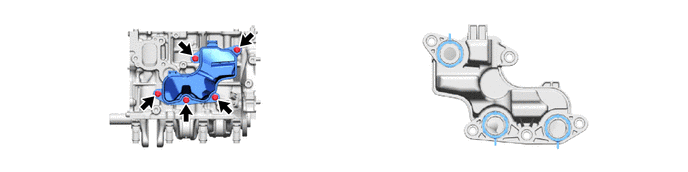
Hide 12211 1.REMOVE NO. 1 VENTILATION CASE

Z101186

NOTICE:

Do not diassembly except if the No. 1 ventilaion case to be damaged.


a.
A460705


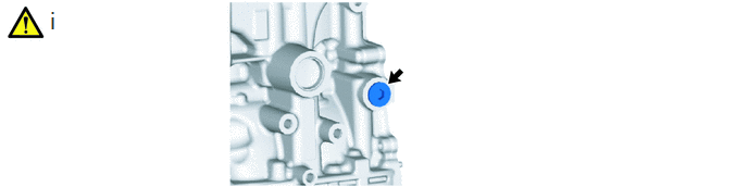
Hide 11432R 2.REMOVE CYLINDER BLOCK WITH HEAD STRAIGHT SCREW PLUG

a.
A460696N02
0.458,0.063 0.74,0.417 0.281,0.354 18 false i

i.

Using a 10 mm hexagon socket wrench, remove the cylinder block with head straight screw plug and gasket from the cylinder.


Hide 3.REMOVE CONNECTING ROD CAP

a.
A461474N01
0.448,0.052 0.729,0.406 0.281,0.354 18 false i 4.458,0.052 4.74,0.406 0.281,0.354 18 false ii

i.

Note the alignment marks on the connecting rod and connecting rod cap so that they can be reinstalled to their original locations.


ii.

Using an E12 "TORX" socket wrench, remove the 2 connecting rod bolts and connecting rod cap.


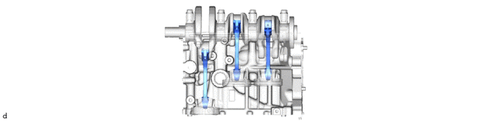
Hide 4.REMOVE PISTON WITH CONNECTING ROD

a.
A461445


Hide 13041 5.REMOVE CONNECTING ROD BEARING
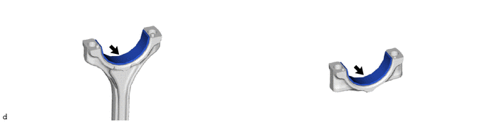
a.
A461490


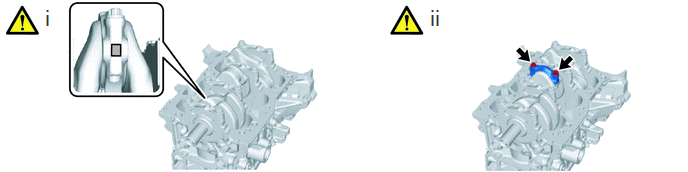
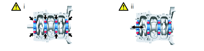
Hide 6.REMOVE CRANKSHAFT BEARING CAP

a.
A460697N01
0.802,0.083 1.146,0.5 0.344,0.417 18 false i 4.573,0.083 4.917,0.5 0.344,0.417 18 false ii

i.

Uniformly loosen and remove the 8 crankshaft bearing cap set bolts.


ii.

Remove the 4 crankshaft bearing caps from the cylinder block sub-assembly.

HINT:

Arrange the removed parts in such a way that they can be reinstalled to their original locations.


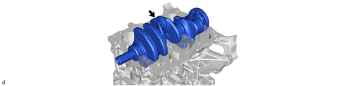
Hide 13411 7.REMOVE CRANKSHAFT

a.
A461492


Hide 11791 8.REMOVE CRANKSHAFT THRUST WASHER

a.
A461998


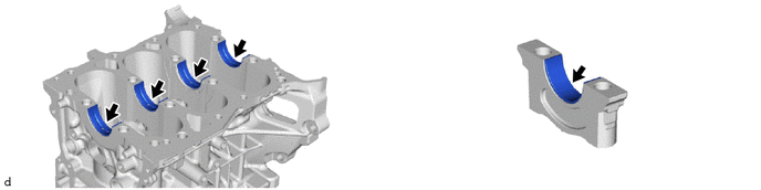
Hide 11711 9.REMOVE CRANKSHAFT BEARING

a.
A461491


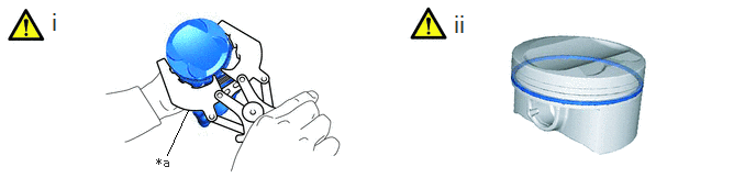
Hide 13011 10.REMOVE PISTON RING SET

a.
A461475C01
1.583,1.469 1.781,1.042 false 1.479,1.469 1.792,1.667 0.313,0.198 10 false *a 0.469,0.073 0.75,0.427 0.281,0.354 18 false i 4.281,0.094 4.563,0.448 0.281,0.354 18 false ii
*a Front Mark Cutout Portion - -


i.

Using a piston ring expander, remove the No. 1 compression ring and No. 2 compression ring from the piston.


ii.

Remove the oil ring expander, upper side rail and lower side rail from the piston by hand.


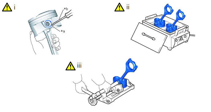
Hide 11.REMOVE PISTON PIN

a.
A461476C01
1.74,0.865 2.031,1.063 true 1.979,0.698 2.146,0.323 true 2.073,0.99 2.385,1.188 0.313,0.198 10 false *a 2.177,0.229 2.49,0.427 0.313,0.198 10 false *b 0.448,0.104 0.729,0.458 0.281,0.354 18 false i 4.271,0.094 4.552,0.448 0.281,0.354 18 false ii 2.594,2.083 2.875,2.438 0.281,0.354 18 false iii
*a Front Mark Cutout Portion *b Protective Tape


i.

Using a screwdriver, pry out the 2 piston pin hole snap rings from the piston.

HINT:

Tape the screwdriver tip before use.


ii.

Gradually heat each piston to between 80 and 90°C (176 to 194°F).

CAUTION:

Be sure to wear protective gloves.


iii.

Using a brass bar and a hammer, lightly tap out the piston pin and remove the connecting rod.

HINT:
·

The piston and piston pin are a matched set.

·

Arrange the removed parts in such a way that they can be reinstalled to their original locations.


Hide 15708 12.REMOVE NO. 1 OIL NOZZLE SUB-ASSEMBLY
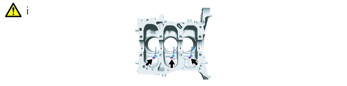
a.
A460699N01
0.521,0.083 0.802,0.438 0.281,0.354 18 false i

i.

Using a 5 mm hexagon wrench, remove the 3 bolts and 3 No. 1 oil nozzle sub-assemblies from the cylinder block sub-assembly.


Hide 13.REMOVE RING PIN

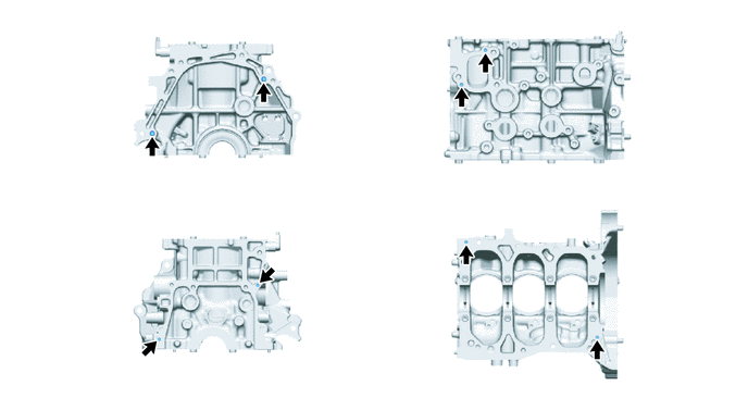
Z101186

NOTICE:

If the ring pin is deformed or damaged, replace it.


a.
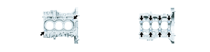
A461952


Hide 14.REMOVE STRAIGHT PIN

Z101186

NOTICE:

If the straight pin is deformed or damaged, replace it.


a.
A461953