Home › Engine / Hybrid System › 2NZ-FE FUEL › FUEL SYSTEM
NM19S0E _51 Engine / Hybrid System _051395 2NZ-FE FUEL _0247860 FUEL SYSTEM UN GENERAL/CONTROL/DETAILS F

2NZ-FE FUEL  FUEL SYSTEM  GENERAL/CONTROL/DETAILS  DETAILS  


FUNCTION


a.

Fuel Returnless System

i.

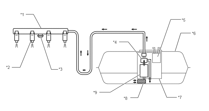
This system is used to reduce the evaporative emission. As shown below, by integrating the fuel filter, pressure regulator, charcoal canister, and fuel sender gauge with fuel pump assembly, it is possible to discontinue the return of fuel from the engine area and prevent temperature rise inside the fuel tank.
W103981E07
1.406,0.969 1.146,0.49 1.146,0.49 0.885,0.49 true 1.073,1.375 0.688,2.313 0.688,2.313 0.406,2.313 false 6,1.771 6.198,1.135 6.198,1.135 6.542,1.135 true 5.406,1.948 5.854,0.667 5.854,0.667 6.208,0.667 true 5.448,2.688 5.719,3.344 5.719,3.344 6.063,3.344 true 4.823,2.542 3.781,3.167 3.781,3.167 3.406,3.167 true 4.875,2.042 4.396,1.438 4.396,1.438 4.083,1.438 true 4.917,2.854 4.729,3.354 4.729,3.354 4.469,3.354 true 1.396,1.271 1.76,2.385 1.76,2.385 1.99,2.385 true 0.698,0.417 0.927,0.667 0.229,0.25 10 false *1 0.208,2.229 0.438,2.479 0.229,0.25 10 false *2 3.198,3.094 3.427,3.344 0.229,0.25 10 false *9 3.875,1.365 4.104,1.615 0.229,0.25 10 false *4 4.24,3.292 4.469,3.542 0.229,0.25 10 false *8 6.229,0.604 6.458,0.854 0.229,0.25 10 false *5 6.583,1.063 6.813,1.313 0.229,0.25 10 false *6 6.104,3.26 6.333,3.51 0.229,0.25 10 false *7 2.01,2.292 2.24,2.542 0.229,0.25 10 false *3

Text in Illustration
*1 Fuel Delivery Pipe Sub-assembly *2 Fuel Injector Assembly
*3 Pulsation Damper *4 Fuel Pressure Regulator Assembly
*5 Canister *6 Fuel Tank Assembly
*7 Fuel Suction with Pump and Gauge Tube Assembly *8 Fuel Filter
*9 Fuel Pump - -


CONSTRUCTION


a.

Fuel Tank Assembly

i.

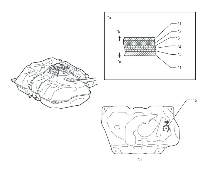
A multiplex layered plastic fuel tank assembly is used. This fuel tank assembly consists of 6 layers of 4 types of materials.


ii.

A fuel drain mark has been provided at the lowest position of the fuel tank assembly. When dismantling (scrapping) the vehicle, drain fuel by drilling a hole at the drain mark.
W105306E03
5.76,4.396 6.427,3.448 6.427,3.448 6.625,3.448 true 5.333,1.875 5.865,2.323 5.865,2.323 6.052,2.323 true 5.344,1.75 5.875,1.875 5.875,1.875 6.073,1.885 true 5.344,1.667 5.875,1.583 5.875,1.583 6.063,1.583 true 5.313,1.604 5.844,1.302 5.844,1.302 6.031,1.302 true 5.323,1.5 5.896,1.094 5.896,1.094 6.083,1.094 true 5.323,1.344 5.896,0.813 5.896,0.813 6.083,0.813 true 6.125,0.74 6.458,0.948 0.333,0.208 10 false *1 6.125,1 6.448,1.208 0.323,0.208 10 false *2 6.063,1.229 6.385,1.438 0.323,0.208 10 false *3 6.115,1.531 6.438,1.74 0.323,0.208 10 false *4 6.125,1.792 6.448,2 0.323,0.208 10 false *3 6.125,2.25 6.448,2.458 0.323,0.208 10 false *1 6.656,3.375 6.979,3.583 0.323,0.208 10 false *5 4.75,5.427 5.073,5.635 0.323,0.208 10 false *d 3.698,0.521 4.021,0.729 0.323,0.208 10 false *a 4.01,1 4.333,1.208 0.323,0.208 10 false *b 4.052,2.042 4.375,2.25 0.323,0.208 10 false *c

Text in Illustration
*1 High Density Polyethylene (HDPE) *2 Regrind Material
*3 Adhesive *4 Ethylene Vinyl Alcohol Copolymer (EVOH)
*5 Fuel Drain Mark - -
*a Fuel Tank Wall Cross Section *b Fuel Tank Assembly Outside
*c Fuel Tank Assembly Inside *d View from Bottom Side


b.

Fuel Pump

i.

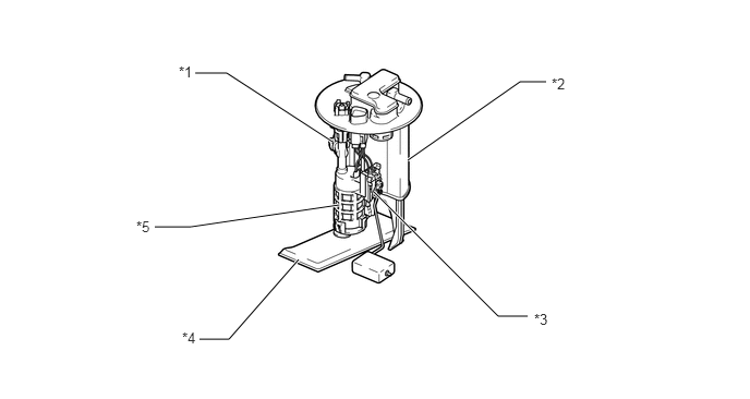
A compact fuel pump, fuel filter, pressure regulator, fuel sender gauge and canister are integrated into the fuel pump assembly.
W103850E04
3.896,1.531 4.969,0.781 4.969,0.781 5.219,0.781 true 3.573,1.833 4.76,3.021 4.76,3.021 5.042,3.021 true 3.177,1.354 2.167,0.698 2.167,0.698 1.865,0.698 true 3.24,1.958 1.823,2.167 1.823,2.167 1.479,2.167 true 2.854,2.479 2.188,3.24 2.188,3.24 1.906,3.24 true 1.708,0.604 1.927,0.854 0.219,0.25 10 false *1 5.271,0.719 5.49,0.969 0.219,0.25 10 false *2 5.104,2.969 5.323,3.219 0.219,0.25 10 false *3 1.74,3.146 1.958,3.396 0.219,0.25 10 false *4 1.302,2.083 1.521,2.333 0.219,0.25 10 false *5

Text in Illustration
*1 Pressure Regulator *2 Canister
*3 Fuel Sender Gauge *4 Fuel Filter
*5 Fuel Pump - -


c.

Fuel Delivery Pipe Sub-assembly

i.

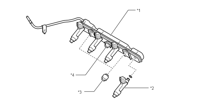
A pressed steel fuel delivery pipe is used.


ii.

Fuel pulsation damper is placed center of the fuel delivery pipe.
W103949E06
3.76,1.219 4.375,0.344 4.375,0.344 4.625,0.344 true 4.188,2.99 5.073,2.99 true 3.656,1.552 2.917,2.552 2.917,2.552 2.583,2.552 true 3.521,2.708 3.208,3.115 3.208,3.115 2.875,3.115 true 4.667,0.271 4.875,0.479 0.208,0.208 10 false *1 5.125,2.917 5.333,3.125 0.208,0.208 10 false *2 2.406,2.469 2.615,2.677 0.208,0.208 10 false *4 2.656,3.052 2.865,3.26 0.208,0.208 10 false *3

Text in Illustration
*1 Fuel Delivery Pipe Sub-assembly *2 Fuel Injector Assembly
*3 Fuel Delivery Spacer *4 Fuel Pulsation Damper


d.

Fuel Injector Assembly

i.

12-holes type fuel injector is used. It's possible to atomize fuel, which prevents the fuel from adhering to the intake port walls and reduces exhaust emissions.
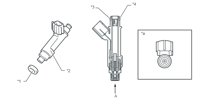
W104989E05
3.917,0.677 3.479,0.281 3.479,0.281 3.385,0.281 true 4.24,0.667 4.531,0.188 4.531,0.188 4.656,0.188 true 1.792,1.802 2.188,2.51 2.188,2.51 2.302,2.51 true 1.156,2.531 0.927,2.896 0.927,2.896 0.833,2.896 true 0.615,2.813 0.854,3 0.24,0.188 10 false *1 2.365,2.438 2.604,2.625 0.24,0.188 10 false *2 3.219,0.167 3.458,0.354 0.24,0.188 10 false *3 4.698,0.063 4.938,0.25 0.24,0.188 10 false *4 5.01,1.104 5.25,1.292 0.24,0.188 10 false *a 4.063,3.344 4.302,3.531 0.24,0.188 9 false A

Text in Illustration
*1 Injector Vibration Insulator *2 Fuel Injector assembly
*3 Fuel Injector O-ring *4 Filter
*a View from A - -