Home › Brake › BRAKE SYSTEM (OTHER) › BRAKE SYSTEM
NM19S0E _54 Brake _051418 BRAKE SYSTEM (OTHER) _0247885 BRAKE SYSTEM UN GENERAL/CONTROL/DETAILS F

BRAKE SYSTEM (OTHER)  BRAKE SYSTEM  GENERAL/CONTROL/DETAILS  DETAILS  


CONSTRUCTION


a.

Brake Assist Mechanism

i.

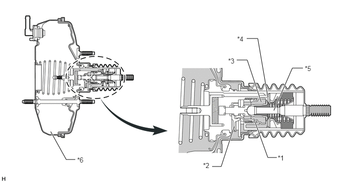
The brake assist mechanism consists of the slide valve, slide valve hook, air valve, control valve and operation rod in the brake booster.
X105978E02
4.865,2.635 4.594,3.469 4.594,3.469 4.406,3.469 true 5.271,2.469 5.563,3.281 5.563,3.281 5.75,3.281 true 1.052,2.74 1.375,3.323 1.375,3.323 1.563,3.323 true 5.688,2.302 6.073,1.417 6.073,1.417 6.292,1.417 true 5.563,2.021 5.354,0.802 5.354,0.802 5.125,0.802 true 5.427,2.125 5.135,1.25 5.135,1.25 4.917,1.25 true 5.771,3.208 6.042,3.458 0.271,0.25 10 false *1 4.219,3.365 4.49,3.615 0.271,0.25 10 false *2 4.74,1.188 5.01,1.438 0.271,0.25 10 false *3 4.927,0.729 5.198,0.979 0.271,0.25 10 false *4 6.333,1.344 6.604,1.594 0.271,0.25 10 false *5 1.604,3.25 1.875,3.5 0.271,0.25 10 false *6

Text in Illustration
*1 Slide Valve *2 Slide Valve Hook
*3 Air Valve *4 Control Valve
*5 Operation Rod *6 Brake Booster


OPERATION


a.

Brake Assist Mechanism

i.

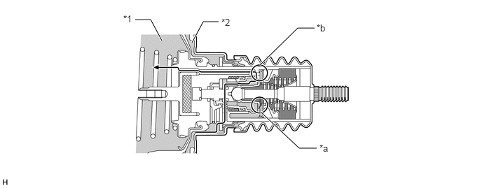
With no braking condition, the air valve closes, the control valve opens, and the pressure is the same in the variable pressure chamber and the constant pressure chamber.
U158761E02
3.865,0.969 4.427,0.417 4.427,0.417 4.677,0.417 true 3.875,1.667 4.448,2.208 4.448,2.208 4.708,2.208 true 2.406,0.604 2.24,0.292 2.24,0.292 2.01,0.292 true 2.854,0.635 3.021,0.323 3.021,0.323 3.25,0.323 true 4.75,2.125 5.021,2.375 0.271,0.25 10 false *a 4.708,0.333 4.979,0.583 0.271,0.25 10 false *b 3.292,0.25 3.563,0.5 0.271,0.25 10 false *2 1.833,0.198 2.104,0.448 0.271,0.25 10 false *1

Text in Illustration
*1 Constant Pressure Chamber *2 Variable Pressure Chamber
*a Air Valve "Close" *b Control Valve "Open"


ii.

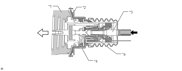
During normal braking, the air valve opens and the control valve closes to activate the brake booster function.
U158762E02
3.865,1.573 4.594,2.125 4.594,2.125 4.781,2.125 true 2.875,0.542 3.021,0.281 3.021,0.281 3.219,0.281 true 2.427,0.49 2.271,0.24 2.271,0.24 2.073,0.24 true 3.052,1.594 3.49,2.385 3.49,2.385 3.677,2.385 true 4.427,1.26 4.865,0.458 4.865,0.458 5.052,0.458 true 3.25,0.208 3.521,0.458 0.271,0.25 10 false *2 1.906,0.167 2.177,0.417 0.271,0.25 10 false *1 5.094,0.396 5.365,0.646 0.271,0.25 10 false *3 4.813,2.052 5.083,2.302 0.271,0.25 10 false *a 3.708,2.333 3.979,2.583 0.271,0.25 10 false *4

Text in Illustration
*1 Constant Pressure Chamber *2 Variable Pressure Chamber
*3 Operation Rod *4 Power Piston
*a Air Valve "Open" - -
V100135

Push
V100136

Move


iii.

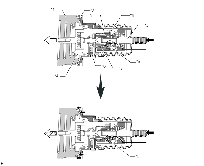
When the operation rod speed is faster than the power piston speed, the air valve pushes the slide valve hook. Consequently, the slide valve separates from the slide valve hook, the spring pushes the control valve, and the control valve closes. Thus, the opening of the air valve becomes enlarged and the air volume that is introduced increases. This results in a brake assist force which strongly pushes the power piston.
U158763E02
3.854,4.958 4.573,5.5 4.573,5.5 4.74,5.5 true 3.875,1.135 4.271,0.542 4.271,0.542 4.552,0.542 true 3.865,1.646 4.583,2.188 4.583,2.188 4.771,2.188 true 2.323,0.604 2.177,0.354 2.177,0.354 1.979,0.354 true 2.813,0.625 2.969,0.365 2.969,0.365 3.156,0.365 true 3.167,1.719 3.354,2.302 3.354,2.302 3.542,2.302 true 3.531,1.594 3.969,2.385 3.969,2.385 4.156,2.385 true 4.458,1.396 4.844,0.885 4.844,0.885 5.031,0.885 true 3.698,1.281 3.521,0.531 3.521,0.531 3.333,0.531 true 2.729,1.896 2.292,2.688 2.292,2.688 2.104,2.688 true 4.792,2.083 5.063,2.333 0.271,0.25 10 false *a 4.771,5.417 5.042,5.667 0.271,0.25 10 false *b 1.917,2.583 2.188,2.833 0.271,0.25 10 false *4 3.583,2.24 3.854,2.49 0.271,0.25 10 false *6 4.188,2.313 4.458,2.563 0.271,0.25 10 false *7 5.083,0.802 5.354,1.052 0.271,0.25 10 false *3 4.573,0.458 4.844,0.708 0.271,0.25 10 false *8 3.156,0.458 3.427,0.708 0.271,0.25 10 false *5 3.177,0.281 3.448,0.458 0.271,0.177 10 false *2 1.792,0.25 2.063,0.5 0.271,0.25 10 false *1

Text in Illustration
*1 Constant Pressure Chamber *2 Variable Pressure Chamber
*3 Operation Rod *4 Power Piston
*5 Air Valve *6 Slide Valve Hook
*7 Slide Valve - -
*a Air Valve "Open" *b Air Valve "Wide Open"
V100135

Push
V100136

Move
V100137

More Move - -