U441E AUTOMATIC TRANSMISSION / TRANSAXLE AUTOMATIC TRANSAXLE SYSTEM GENERAL/CONTROL/DETAILS DETAILS
FUNCTION OF MAIN COMPONENTS
The main components of the U441E automatic transaxle system are as follows:
| Component | Function |
|---|---|
| Forward Clutch (C1) | Connects the input shaft assembly and planetary sun gear sub-assembly. |
| Direct Clutch (C2) | Connects the input shaft assembly and planetary carrier. |
| Reverse Clutch (C3) | Connects the input shaft assembly and rear planetary sun gear assembly. |
| OD and 2nd Brake (B1) | Locks the rear planetary sun gear assembly. |
| 2nd Brake (B2) | Prevents the rear planetary sun gear assembly from turning counterclockwise. |
| 1st and Reverse Brake (B3) | Locks the planetary carrier. |
| No. 1 1-way Clutch (F1) | Prevents the rear planetary sun gear assembly from turning counterclockwise. |
| No. 2 1-way Clutch (F2) | Prevents the planetary carrier from turning counterclockwise. |
| Planetary Gears | These gears change the route through which driving force is transmitted, in accordance with the operation of both clutch and brake, in order to increase or reduce the input and output speed. |
| Shift Solenoid Valve S1 | ·
Switches the 2-3 shift valve. ·
Controls the C2 clutch. |
| Shift Solenoid Valve S2 | ·
Switches the 1-2 and 3-4 shift valves. ·
Controls the C1 clutch and 2 brakes (B1 and B2). |
| Shift Solenoid Valve ST | Switches the 3-4 and 4-3 shift timing valves. |
| Shift Solenoid Valve SL | Controls the lock-up clutch. |
| Shift Solenoid Valve SLT | ·
Controls the line pressure. ·
Controls the secondary pressure. ·
Controls the accumulator backpressure. |
| ATF Temperature Sensor (Transmission Wire) | Detects the ATF temperature. |
| Speed Sensor NT (Transmission Revolution Sensor) | Detects the input speed of the transaxle. |
| Park/Neutral Position Switch Assembly | Detects the shift lever position. |
| Transmission Control Switch | Detects the shift lever in 3 position. |
| Shift Lock Control ECU Sub-assembly | Controls the shift lock system. |
| Stop Light Switch Assembly | Detects the brake pedal depressed. |
| Combination Meter Assembly | Detects the vehicle speed signal. |
| MIL | Illuminates or blinks to inform the driver when the ECM detects a malfunction. |
| Shift Position Indicator | Indicates the shift lever position. |
| ECM | ·
Controls each shift solenoid valve and engine output in response to a signal from each sensor and switch. ·
When the ECM detects a malfunction, it makes a diagnosis and memorizes the failed section. |
SYSTEM CONTROL
Automatic Transaxle Controls List
| Control | Outline |
|---|---|
| Clutch to Clutch Pressure Control | Calculates an environmentally favorable shift position based on the driving conditions of the vehicle, and gives shifting recommendation. |
| Clutch Pressure Control | The shift solenoid valve SLT minutely controls the clutch pressure in accordance with the engine output and driving conditions. |
| Line Pressure Control | Actuates the shift solenoid valve SLT to control the line pressure in accordance with information from the ECM and the operating conditions of the transaxle. |
| Shift Control in Uphill/Downhill Traveling | Restricts 4th upshift and provides appropriate engine braking by using the ECM to determine whether the vehicle is traveling uphill or downhill. |
| Shift Timing Control | ·
The ECM sends a current to the shift solenoid valve S1 and/or S2 based on the signals from each sensor and shifts the gear. ·
The shift solenoid valves minutely control the clutch pressure in accordance with the engine output and driving conditions. |
| Lock-up Timing Control | The ECM sends current to the shift solenoid valve SL based on the signals from each sensor and engages or disengages the lock-up clutch. |
| Engine Torque Control | Temporarily retards the engine ignition timing to restrict the output torque, thus ensuring the shift feel during up or down shifting. |
| "N" to "D" Squat Control | When the shift lever is shifted from the "N" to "D" position, the gear is temporarily shifted to the 3rd and then to the 1st to reduce vehicle squat. |
| Shift Lock System | The shift lock mechanism prevents the shift lever from being moved to any position other than P, unless the ignition switch is ON, and the brake pedal is depressed. |
| Fail-safe | Even if a malfunction is detected in the sensors or solenoids, the ECM effects fail-safe control to prevent the vehicle's drivability from being affected significantly. |
| Diagnosis | When the ECM detects a malfunction, the ECM makes a diagnosis and memorizes the failed section. |
Clutch to Clutch Pressure Control
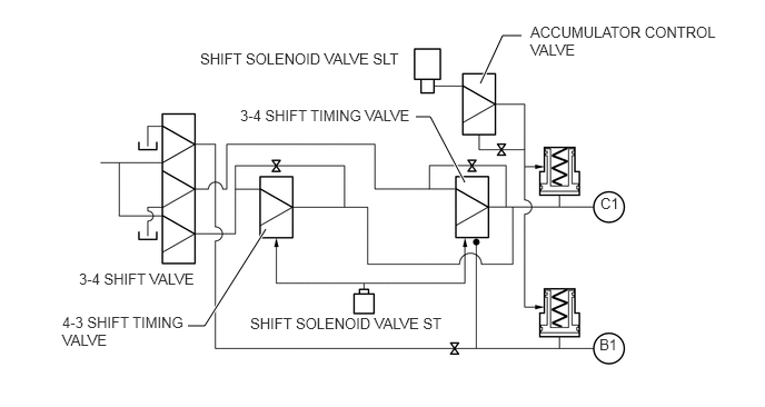
This control is used for shifting from 3rd to 4th gear, and from 4th to 3rd gear. It actuates shift solenoid valves ST and SLT in accordance with the signals from the ECM, and guides this output pressure directly to the 4-3 shift timing valve and the 3-4 shift timing valve in order to regulate the line pressure that acts on the B1 brake (OD and 2nd brake) and C1 clutch (forward clutch).
As a result, compact B1 and C1 accumulators without a backpressure chamber have been realized.
Clutch Pressure Control
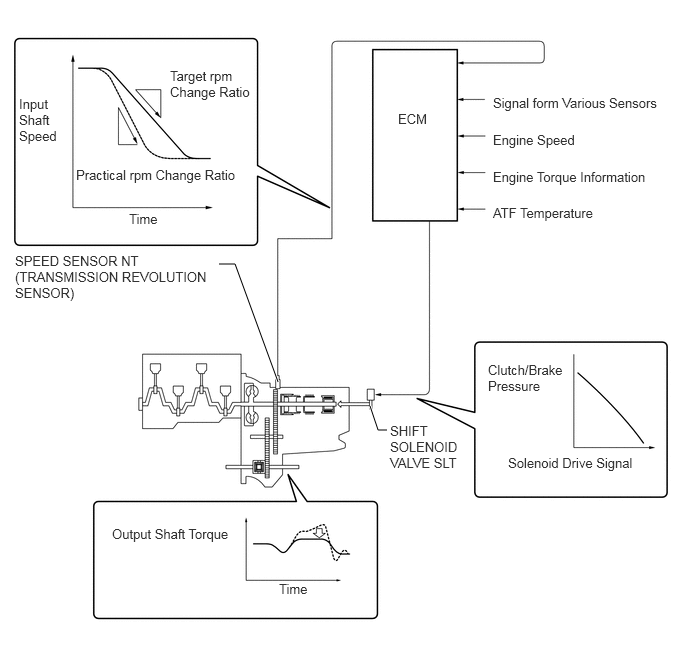
The ECM monitors the signals from various types of sensor such as the speed sensor NT (transmission revolution sensor), allowing shift solenoid valve SLT to minutely control the clutch pressure in accordance with engine output and driving conditions. As a result, smooth shift characteristics have been realized.
Line Pressure Control
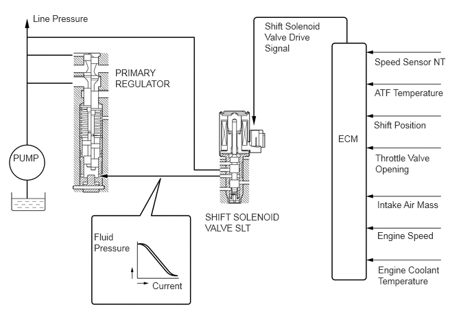
Through the use of the shift solenoid valve SLT, the line pressure is appropriately controlled in accordance with the engine torque information, as well as with the internal operating conditions of the torque converter assembly and the transaxle.
Accordingly, the line pressure can be controlled minutely in accordance with the engine output, traveling condition and the ATF temperature, thus realizing smooth shift characteristics and regulating the workload in the oil pump.
Shift Control in Uphill/Downhill Traveling
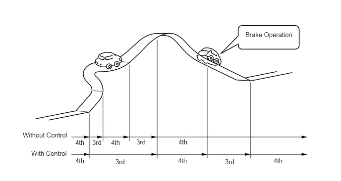
This control helps minimize the gear shifting when the driver operates the accelerator pedal while driving on a winding uphill or downhill road in order to ensure a smooth drive.
When the ECM detects uphill travel, it prohibits upshifting to 4th after downshifting to 3rd.
If a signal indicating that the driver has operated the brake pedal is input while the ECM detects downhill travel, it downshifts from 4th to 3rd.
The actual acceleration calculated from the speed sensor signal is compared with the reference acceleration (based on level road travel) stored in the ECM to determine uphill or downhill travel.

| *a | Smaller | - | - |

|
Reference Acceleration | 
|
Actual Acceleration |

| *a | Greater | - | - |
|
|
Reference Acceleration |
|
Actual Acceleration |
Shift Lock System
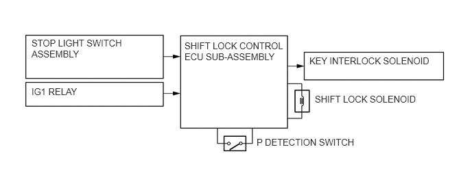
The key interlock device prevents the key from being pulled out after the ignition switch is turned OFF, unless the shift lever is moved to the P position. Thus, the driver is urged to park the vehicle in the P position.
The shift lock mechanism prevents the shift lever from being shifted to a position other than the P position, unless the ignition switch is ON and the brake pedal is depressed. It prevents the vehicle from starting off suddenly.
The shift lock control ECU sub-assembly uses the P detection switch to detect the shift lever position, and receives input signals from the stop light switch assembly and ignition switch. Upon receiving these signals, the shift lock control ECU sub-assembly turns on the key interlock solenoid and the shift lock solenoid in order to release the key interlock and shift lock.
A shift lock release button, which manually overrides the shift lock mechanism, is used.
CONSTRUCTION
Torque Converter Assembly
The torque converter assembly has appropriately torque ratio and designed fluid passages and impeller configuration, resulting in substantially enhanced transmission efficiency to ensure good starting, acceleration and fuel economy.
Furthermore, a hydraulically operated lock-up mechanism which cuts power transmission losses due to slippage at medium and high speeds is used.
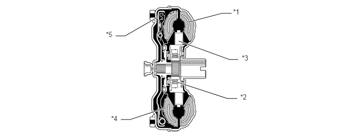
| *1 | Pump Impeller | *2 | 1-way Clutch |
| *3 | Stator | *4 | Turbine Runner |
| *5 | Lock-up Clutch | - | - |
Oil Pump
The oil pump is operated by the torque converter assembly. It lubricates the planetary gear units and supplies operating fluid pressure to the hydraulic control.
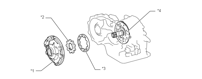
| *1 | Front Oil Pump Body | *2 | Front Oil Pump Drive Gear |
| *3 | Front Oil Pump Driven Gear | *4 | Stator Shaft Assembly |
Planetary Gear Unit
A ravigneaux type planetary gear is used in the planetary gear unit which is located on the input shaft. This planetary gear combines a set of sun gears with 2 different diameters and a short pinion gear and a long pinion gear.
A centrifugal fluid pressure canceling mechanism is used in the C1 clutch which is applied when downshifting from 4th.
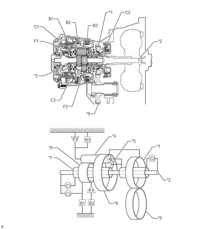
| *1 | Counter Drive Gear | *2 | Input Shaft Assembly |
| *3 | Planetary Gear Assembly | *4 | Long Pinion Gear (Planetary Gear Assembly) |
| *5 | Short Pinion Gear (Planetary Gear Assembly) | *6 | Planetary Ring Gear |
| *7 | Planetary Sun Gear Sub-assembly | *8 | Rear Planetary Sun Gear Assembly |
| *9 | Counter Driven Gear | - | - |
The functions of the clutches and brakes are as follows:
| Component | Function | |
|---|---|---|
| C1 | Forward Clutch | Connects the input shaft assembly and planetary sun gear sub-assembly. |
| C2 | Direct Clutch | Connects the input shaft assembly and planetary carrier. |
| C3 | Reverse Clutch | Connects the input shaft assembly and rear planetary sun gear sub-assembly. |
| B1 | OD and 2nd Brake | Locks the rear planetary sun gear assembly. |
| B2 | 2nd Brake | Prevents the rear planetary sun gear assembly from turning counterclockwise. |
| B3 | 1st and Reverse Brake | Locks the planetary carrier. |
| F1 | No. 1 1-way Clutch | Prevents the rear planetary sun gear assembly from turning counterclockwise. |
| F2 | No. 2 1-way Clutch | Prevents the planetary carrier from turning counterclockwise. |
| Planetary Gears | This gear changes the route through which driving force is transmitted, in accordance with the operation of both clutch and brake, in order to increase or reduce the input and output speed. | |
Centrifugal Fluid Pressure Canceling Mechanism
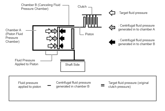
During shifting, in addition to the fluid pressure controlled by the valve body, the fluid pressure generated by centrifugal force (centrifugal fluid pressure) in chamber A also acts on the piston, and causes an increase in shifting shock generated by revolution differences between the input and output parts of the clutch by speeding the clutch engagement.
In order to improve the shifting characteristics for 4-3 and 3-4 shifting for which high responsiveness is required, a centrifugal fluid pressure canceling mechanism is applied.
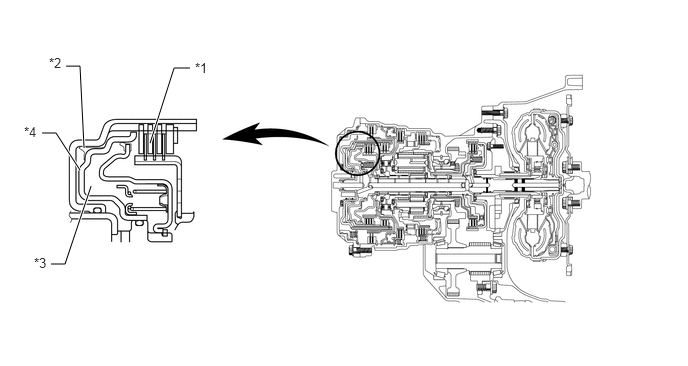
| *1 | C1 Clutch | *2 | Chamber A |
| *3 | Chamber B | *4 | Piston |
The canceling fluid pressure canceling mechanism is a chamber (chamber B) located opposite to chamber A. By filling chamber B with shaft lubrication fluid, an equal amount of centrifugal fluid pressure is generated there and works against the centrifugal fluid pressure in chamber A.
Transmission Valve Body Assembly
The valve body consists of the upper and lower valve bodies and 5 shift solenoid valves.
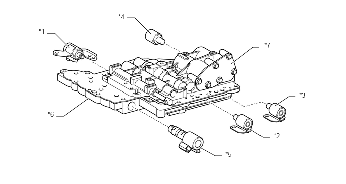
| *1 | Shift Solenoid Valve SL | *2 | Shift Solenoid Valve S2 |
| *3 | Shift Solenoid Valve S1 | *4 | Shift Solenoid Valve ST |
| *5 | Shift Solenoid Valve SLT | *6 | Lower Valve Body |
| *7 | Upper Valve Body | - | - |
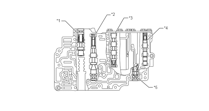
| *1 | Reverse Control Valve | *2 | Secondary Regulator Valve |
| *3 | 3-4 Shift Valve | *4 | 3-4 Shift Timing Valve |
| *5 | Check Valve | - | - |
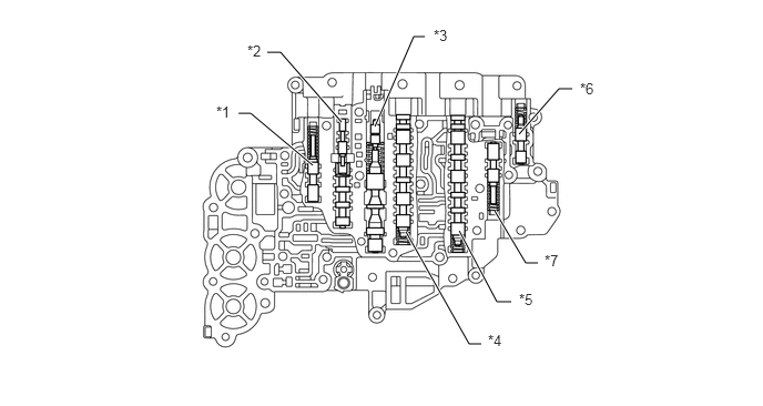
| *1 | Solenoid Modulator Valve | *2 | Lock-up Relay Valve |
| *3 | Primary Regulator Valve | *4 | 1-2 Shift Valve |
| *5 | 2-3 Shift Valve | *6 | 4-3 Shift Timing Valve |
| *7 | Low Coast Modulator Valve | - | - |
Shift Solenoid Valve SLT
In order to supply hydraulic pressure proportional to the current that flows to the solenoid coil, shift solenoid valve SLT is provided.
The valve linearly controls the line pressure, secondary pressure and accumulator backpressure based on the signals from the ECM.
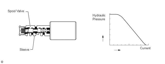
| Shift Solenoid Valve | Function |
|---|---|
| SLT | ·
Line pressure control ·
Secondary pressure control ·
Accumulator backpressure control |
Shift Solenoid Valve ST
This shift solenoid valve uses a 2-way solenoid valve.
A filter is provided at the tip of the solenoid valve to further improve operational reliability.
There are 2 types of shift solenoid valve ST. The valve structures are different, but the basic operations are the same.
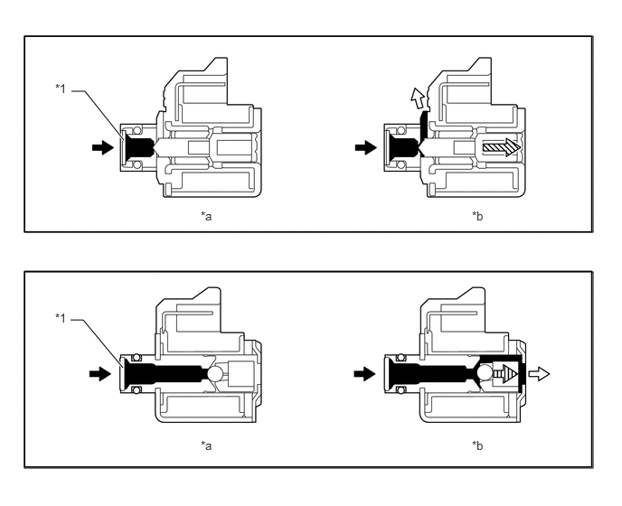
| *1 | Filter | - | - |
| *a | Off Condition | *b | On Condition |
|
|
Line Pressure |
|
Drain |

|
Plunger Moving Direction | 
|
Cylinder Ball Moving Direction |
| Shift Solenoid Valve | Function |
|---|---|
| ST | 3-4 and 4-3 shift timing valves switching |
Shift Solenoid Valves S1, S2 and SL
These shift solenoid valves use a 2-way solenoid valve.
A filter is provided at the tip of the solenoid valve to further improve operational reliability.
There are 2 types of shift solenoid valve, of which the valve structures are different but the basic operations are the same, for S1, S2 and SL respectively.
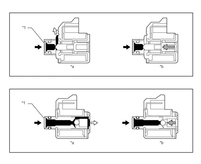
| *1 | Filter | - | - |
| *a | Off Condition | *b | On Condition |
|
|
Line Pressure |
|
Drain |
|
|
Plunger Moving Direction |
|
Cylinder Ball Moving Direction |
| Shift Solenoid Valve | Function |
|---|---|
| S1 | ·
2-3 shift valve switching ·
C2 clutch control |
| S2 | ·
1-2 and 3-4 shift valves switching ·
C1 clutch and 2-brake (B1 and B2) control |
| SL | Lock-up clutch control |
ATF Temperature Sensor (Transmission Wire)
The ATF temperature sensor (transmission wire) is installed in the lower valve body for direct detection of the fluid temperature.
The ATF temperature sensor (transmission wire) is used for the correction of clutch and brake pressures to give smooth shift quality every time.
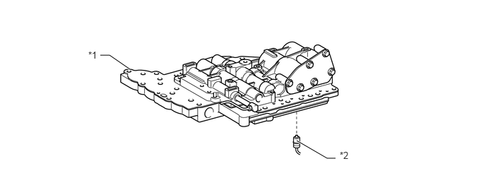
| *1 | Lower Valve Body | *2 | ATF Temperature Sensor (Transmission Wire) |
Speed Sensor NT (Transmission Revolution Sensor)
The speed sensor NT (transmission revolution sensor) detects the input speed of the transaxle. The forward clutch (C2) drum is used as the timing rotor for this sensor. Thus, the ECM can detect shift timing of the gears and appropriately control the engine torque and hydraulic pressure in response to the various conditions.
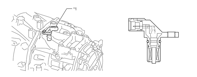
| *1 | Speed Sensor NT (Transmission Revolution Sensor) | - | - |
Shift Control Mechanism
A gate type shift lever that uses a transmission control cable is used.
The shift control mechanism consists of a shift lock control unit assembly and a transmission control cable assembly.
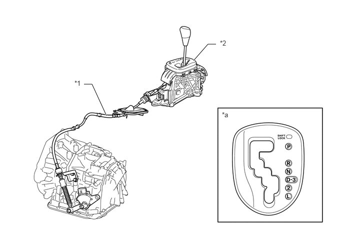
| *1 | Transmission Control Cable Assembly | *2 | Shift Lock Control Unit Assembly |
| *a | Shift Pattern | - | - |
Park/Neutral Position Switch Assembly and Transmission Control Switch
The park/neutral position switch assembly sends the P, R, N, D, 2 and L position signals to the ECM.
The transmission control switch sends the 3 position signal to the ECM.
The ECM controls the automatic transaxle system in accordance with the shift lever position signals.
The ECM transmits signals to the combination meter assembly for the shift position indicator (P, R, N, D, 2, 3 and L) in response to the signals received from the switches.
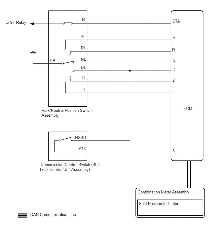
OPERATION
Transmission Power Flow
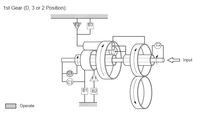
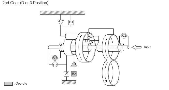
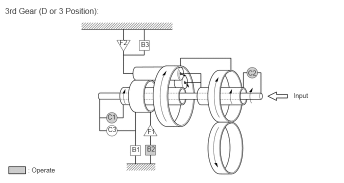
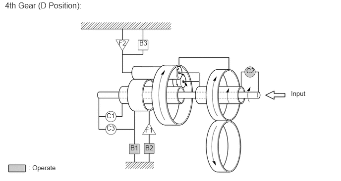
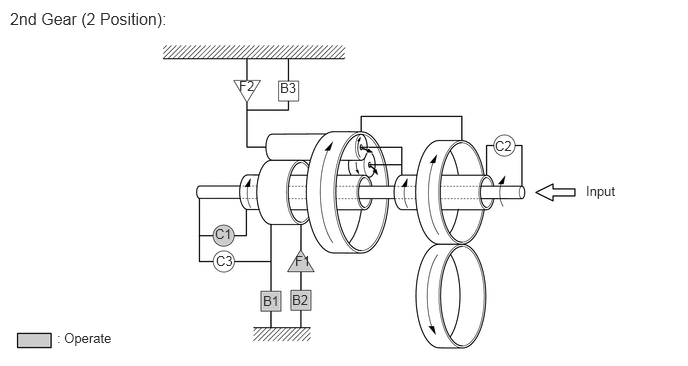
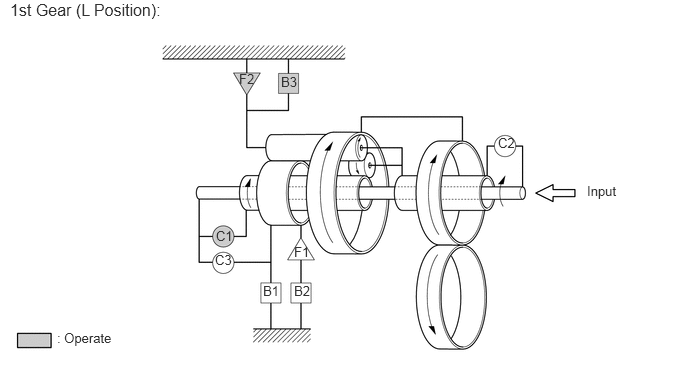
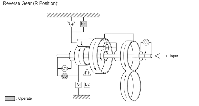
| Shift Lever Position | Gear | Solenoid Valve | Clutch | Brake | 1-way Clutch | ||||||
|---|---|---|---|---|---|---|---|---|---|---|---|
| S1 | S2 | C1 | C2 | C3 | B1 | B2 | B3 | F1 | F2 | ||
| P | Park | On | On | - | - | - | - | - | - | - | - |
| R | Reverse | On | On | - | - | ○ | - | - | ○ | - | - |
| N | Neutral | On | On | - | - | - | - | - | - | - | - |
| D | 1st | On | On | ○ | - | - | - | - | - | - | ○ |
| 2nd | On | Off | ○ | - | - | - | ○ | - | ○ | - | |
| 3rd | Off | Off | ○ | ○ | - | - | ○ | - | - | - | |
| 4th | Off | On | - | ○ | - | ○ | ○ | - | - | - | |
| 3 | 1st | On | On | ○ | - | - | - | - | - | - | ○ |
| 2nd | On | Off | ○ | - | - | - | ○ | - | ○ | - | |
| 3rd | Off | Off | ○ | ○ | - | - | ○ | - | - | - | |
| 2 | 1st | On | On | ○ | - | - | - | - | - | - | ○ |
| 2nd | On | Off | ○ | - | - | ○ | ○ | - | ○ | - | |
| L | 1st | On | On | ○ | - | - | - | - | ○ | - | ○ |
- HINT:
-
○: Operation
-
-: Not operation
FAIL-SAFE
The fail-safe function minimizes the loss of operability when an abnormality occurs in a sensor or shift solenoid valve.
| Malfunction Part | Function |
|---|---|
| Vehicle Speed Signal | During a vehicle speed signal malfunction, the 4th upshift is prohibited. |
| Speed Sensor NT (Transmission Revolution Sensor) | During a speed sensor NT (transmission revolution sensor) signal malfunction, the 4th upshift is prohibited. |
| ATF Temperature Sensor (Transmission Wire) | During a ATF temperature sensor (transmission wire) malfunction, the 4th upshift is prohibited. |
| Shift Solenoid Valve SLT or ST | During a shift solenoid valve SLT or ST malfunction, the 4th upshift is prohibited. |
| E.F.I. Engine Coolant Temperature Sensor, Knock Control Sensor or Throttle Position Sensor | During an E.F.I. engine coolant temperature sensor, knock control sensor or throttle position sensor malfunction, the 4th upshift is prohibited. |
| Shift Solenoid Valve S1 or S2 | During a malfunction in the shift solenoid valve S1 or S2, the current to the faulty shift solenoid valve is cut off and control is effected by operating the normal shift solenoid valves. Shift control is effected as described in the table below, depending on the failed shift solenoid valve. |
DIAGNOSIS
When the ECM detects a malfunction, the ECM records the malfunction and memorizes the information related to the fault. Furthermore, the ECM illuminates or blinks the MIL in the combination meter assembly to inform the driver.
The ECM will also store the Diagnostic Trouble Codes (DTCs) of the malfunctions. The DTCs stored in the ECM are output to the intelligent tester via the ECM and the DLC3.
For details, refer to the Repair Manual.