2NZ-FE ENGINE MECHANICAL CYLINDER HEAD REPLACEMENT
PROCEDURE

 11122
1.REMOVE INTAKE VALVE GUIDE BUSH
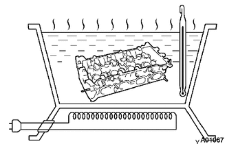
Heat the cylinder head to 80 to 100°C (176 to 212°F).
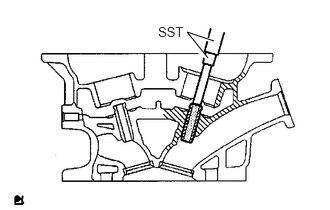
Using SST and a hammer, tap out the guide bushing.
- SST
- 09201-10000 (09201-01050)
09950-70010 (09951-07100)
11126
2.REMOVE EXHAUST VALVE GUIDE BUSH
Heat the cylinder head to 80 to 100°C (176 to 212°F).
Using SST and a hammer, tap out the guide bushing.
- SST
- 09201-10000 (09201-01050)
09950-70010 (09951-07100)
11122
3.INSTALL INTAKE VALVE GUIDE BUSH
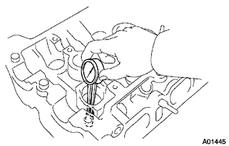
Using a caliper gauge, measure the bushing bore diameter of the cylinder head.
- Inside diameter:
9.685 to 9.706 mm (0.3813 to 0.3821 in.)
If the bushing bore diameter of the cylinder head is greater than 9.706 mm (0.3821 in.), machine the bushing bore to the dimension of 9.735 to 9.755 mm (0.3833 to 0.3841 in.).
| Bushing bore diameter
mm (in.) |
Bushing size |
|---|---|
| 9.685 to 9.706
(0.3813 to 0.3821) |
STD |
| 9.735 to 9.755
(0.3833 to 0.3841) |
O/S 0.05 |
Heat the cylinder head to 80 to 100°C (176 to 212°F).
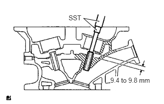
Using SST and a hammer, tap a new guide bushing in to the specified protrusion height.
- SST
- 09201-10000 (09201-01050)
09950-70010 (09951-07100)
- Protrusion height:
9.0 to 9.4 mm (0.354 to 0.370 in.)
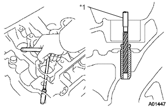
Using a sharp 5 mm reamer, ream the guide bushing to obtain the standard oil clearance between the guide bushing and valve stem.
| *1 | Reamer |
- Standard oil clearance:
0.025 to 0.060 mm (0.0010 to 0.0024 in.)
11126
4.INSTALL EXHAUST VALVE GUIDE BUSH
Using a caliper gauge, measure the bushing bore diameter of the cylinder head.
- Inside diameter:
9.685 to 9.706 mm (0.3813 to 0.3821 in.)
If the bushing bore diameter of the cylinder head is greater than 9.706 mm (0.3821 in.), machine the bushing bore to the dimension of 9.735 to 9.755 mm (0.3833 to 0.3841 in.)
| Bushing bore diameter
mm (in.) |
Bushing size |
|---|---|
| 9.685 to 9.706
(0.3813 to 0.3821) |
STD |
| 9.735 to 9.755
(0.3833 to 0.3841) |
O/S 0.05 |
Heat the cylinder head to 80 to 100°C (176 to 212°F).
Using SST and a hammer, tap a new guide bushing in to the specified protrusion height.
- SST
- 09201-10000 (09201-01050)
09950-70010 (09951-07100)
- Protrusion height:
9.0 to 9.4 mm (0.354 to 0.370 in.)
Using a sharp 5 mm reamer, ream the guide bushing to obtain the standard oil clearance between the guide bushing and valve stem.
- Standard oil clearance:
0.030 to 0.065 mm (0.0012 to 0.0026 in.)