RM19S0E
_51
Engine / Hybrid System
_051454
1NZ-FE EMISSION CONTROL
_0248102
PURGE VALVE
G
1NZ-FE EMISSION CONTROL PURGE VALVE INSPECTION
PROCEDURE

 25860
1.INSPECT NO. 1 VACUUM SWITCHING VALVE ASSEMBLY
a.
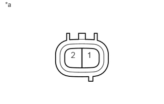
Check the resistance.
i.
0.108,0.01 0.368,0.191
0.260,0.181
10
*a
1.486,1.054 1.652,1.270
0.165,0.216
12
2
1.826,1.054 1.991,1.270
0.165,0.216
12
1
Measure the resistance according to the value(s) in the table below.
| *a | Component without harness connected
(No. 1 Vacuum Switching Valve Assembly) |
- Standard Resistance:
Tester Connection Condition Specified Condition 1 - 2 20°C (68°F) 23 to 26 Ω
If the result is not as specified, replace the No. 1 vacuum switching valve assembly.
b.
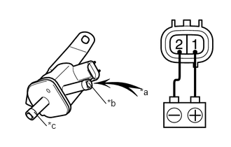
Check the operation.
i.
2.08,1.282 2.389,1.500
0.309,0.218
10
*a
1.595,1.449 1.903,1.667
0.309,0.218
10
*b
1.316,1.229 1.579,1.542
false
0.71,1.78 1.019,1.999
0.309,0.218
10
*c
0.507,1.665 0.694,1.874
false
Apply battery voltage between the terminals of the No. 1 vacuum switching valve assembly and check that the following occurs when blowing air into port E.
| *a | Air |
| *b | Port E |
| *c | Port F |
- OK:
Condition Specified Condition Battery voltage applied to terminals 1 and 2 Air flows from port F. Battery voltage not applied to terminals 1 and 2 Air does not flow.
If the result is not as specified, replace the No. 1 vacuum switching valve assembly.