RM19S0E
_52
Drivetrain
_051465
U340E AUTOMATIC TRANSMISSION / TRANSAXLE
_0248156
AUTOMATIC TRANSAXLE SYSTEM
C
U340E AUTOMATIC TRANSMISSION / TRANSAXLE AUTOMATIC TRANSAXLE SYSTEM P2716 Pressure Control Solenoid "D" Electrical (Shift Solenoid Valve SLT)
DESCRIPTION
Refer to P2714 (See page Drivetrain>U340E (AUTOMATIC TRANSMISSION / TRANSAXLE)>AUTOMATIC TRANSAXLE SYSTEM>P2714).
| DTC No. | DTC Detection Condition | Trouble Area |
|---|---|---|
| P2716 | Open or short is detected in shift solenoid valve SLT circuit for 1 second or more while driving (1 trip detecting logic). | ·
Wire harness or connector ·
Transmission wire ·
Shift solenoid valve SLT ·
ECM |
MONITOR DESCRIPTION
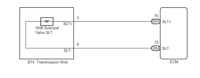
When an open or short in the linear solenoid valve (SLT) circuit is detected, the ECM interprets this as a fault. The ECM turns on the MIL and stores the DTC.
WIRING DIAGRAM
0.99,2.146 1.271,2.323
0.281,0.177
10
false
B74
1.313,2.146 2.5,2.323
1.188,0.177
10
false
Transmission Wire
2.271,0.771 2.656,0.927
0.385,0.156
10
false
SLT+
2.75,0.563 2.885,0.74
0.135,0.177
10
false
3
2.281,1.729 2.635,1.885
0.354,0.156
10
false
SLT-
2.75,1.51 2.885,1.688
0.135,0.177
10
false
8
5.521,0.479 5.698,0.646
0.177,0.167
10
false
76
5.458,0.677 5.771,0.833
0.313,0.156
10
false
B84
5.531,1.438 5.708,1.604
0.177,0.167
10
false
75
5.469,1.646 5.781,1.802
0.313,0.156
10
false
B84
5.813,0.698 6.219,0.854
0.406,0.156
10
false
SLT+
5.813,1.656 6.219,1.813
0.406,0.156
10
false
SLT-
6.083,2.135 6.438,2.313
0.354,0.177
10
false
ECM
1.271,0.917 2.146,1.229
0.875,0.313
10
false
Shift Solenoid Valve SLT
PROCEDURE
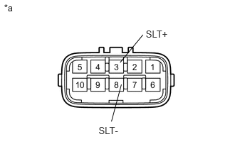
1.INSPECT TRANSMISSION WIRE (SHIFT SOLENOID VALVE SLT)
2.132,0.42 2.530,0.579
0.398,0.158
10
SLT+
1.442,1.837 1.834,1.998
0.392,0.161
10
SLT-
1.757,0.917 2.091,0.51
false
1.775,1.24 1.63,1.783
false
0.059,0.028 0.256,0.192
0.197,0.164
10
*a
a.
Disconnect the transmission wire connector from the transaxle.
b.
Measure the resistance according to the value(s) in the table below.
- Standard Resistance:
Tester Connection Condition Specified Condition 3 (SLT+) - 8 (SLT-) 20°C (68°F) 5.0 to 5.6 Ω 3 (SLT+) - Body ground Always 10 kΩ or higher 8 (SLT-) - Body ground Always 10 kΩ or higher
| *a | Component without harness connected
(Transmission Wire) |
OK
2.CHECK HARNESS AND CONNECTOR (TRANSMISSION WIRE - ECM)
NG
3.INSPECT SHIFT SOLENOID VALVE SLT
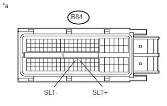
2.CHECK HARNESS AND CONNECTOR (TRANSMISSION WIRE - ECM)
1.46,0.26 1.763,0.427
0.303,0.167
10
B84
0.048,0.027 0.258,0.210
0.210,0.182
10
*a
1.902,1.822 2.265,1.973
0.363,0.150
10
SLT+
1.64,1.242 2.109,1.794
false
0.905,1.822 1.268,1.973
0.363,0.150
10
SLT-
1.554,1.242 1.113,1.794
false
a.
Connect the transmission wire connector to the transaxle.
b.
Disconnect the ECM connector.
c.
Measure the resistance according to the value(s) in the table below.
- Standard Resistance:
Tester Connection Condition Specified Condition B84-76 (SLT+) - B84-75 (SLT-) 20°C (68°F) 5.0 to 5.6 Ω B84-76 (SLT+) - Body ground Always 10 kΩ or higher B84-75 (SLT-) - Body ground Always 10 kΩ or higher
| *a | Front view of wire harness connector
(to ECM) |
OK
NG
REPAIR OR REPLACE HARNESS OR CONNECTOR
3.INSPECT SHIFT SOLENOID VALVE SLT
OK
REPLACE TRANSMISSION WIRE
NG
REPLACE SHIFT SOLENOID VALVE SLT