RM19S0E
_52
Drivetrain
_051466
U441E AUTOMATIC TRANSMISSION / TRANSAXLE
_0248172
SPEED SENSOR(w/o ABS)
G
U441E AUTOMATIC TRANSMISSION / TRANSAXLE SPEED SENSOR(w/o ABS) INSPECTION
PROCEDURE

 89413B
1.INSPECT TRANSMISSION REVOLUTION SENSOR
a.
0.187,0.08 0.367,0.241
0.180,0.160
10
*a
2.368,1.764 2.507,1.925
0.139,0.162
10
1
0.982,1.764 1.122,1.925
0.139,0.162
10
2
1.058,1.764 1.445,1.217
false
2.412,1.764 1.993,1.208
false
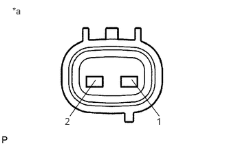
Measure the resistance according to the value(s) in the table below.
| *a | Component without harness connected
(Transmission Revolution Sensor) |
- Standard Resistance:
Tester Connection Condition Specified Condition 1 - 2 20°C (68°F) 560 to 680 Ω
If the resistance value is not as specified, replace the transmission revolution sensor.
83181G
2.INSPECT SPEEDOMETER SENSOR
a.
0.927,0.875 1.51,0.875
true
1.688,0.854 0.938,0.552
true
1.844,0.854 0.948,0.229
true
0.771,0.792 0.875,0.99
0.104,0.198
10
false
1
0.792,0.438 0.885,0.646
0.094,0.208
10
false
2
0.844,0.073 0.927,0.271
0.083,0.198
10
false
3
0.177,0.115 0.333,0.292
0.156,0.177
10
false
*a
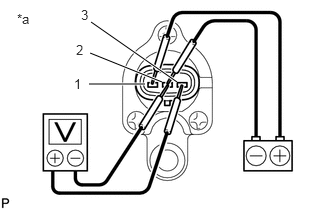
Connect the positive (+) lead from the battery to terminal 1 and the negative (-) lead to terminal 2.
| *a | Component without harness connected
(Speedometer Sensor) |
b.
Connect the positive (+) lead from the tester to terminal 3 and the negative (-) lead to terminal 2.
c.
Rotate the shaft.
d.
Check that the voltage output varies between 0 V and 11 V between terminals 2 and 3.
- HINT:
-
The voltage output oscillates more than 4 times every revolution of the speedometer sensor shaft.
If the operation is not as specified, replace the speedometer sensor.