U441E AUTOMATIC TRANSMISSION / TRANSAXLE SHIFT LEVER REASSEMBLY
PROCEDURE

 35974
1.INSTALL LOWER POSITION INDICATOR HOUSING
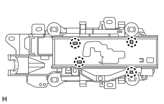
Engage the 4 claws and install the lower position indicator housing to the shift lock control unit assembly.
33550E
2.INSTALL POSITION INDICATOR LIGHT CAP
Install the position indicator light cap to the position indicator light bulb.
33550D
3.INSTALL POSITION INDICATOR LIGHT BULB
Install the position indicator light bulb to the indicator light wire sub-assembly.
35906
4.INSTALL INDICATOR LIGHT WIRE SUB-ASSEMBLY
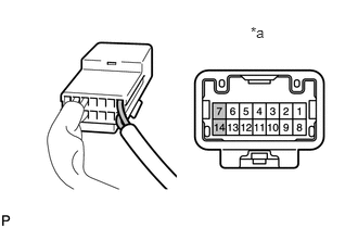
Install the indicator light wire sub-assembly to terminals 7 and 14 of the transmission control switch connector.
| *a | Component without harness connected
(Transmission Control Switch) |
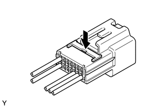
Push down the terminal retainer of the transmission control switch connector to lock it.
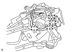
Engage the 4 clamps and install the indicator light wire sub-assembly to the shift lock control unit assembly.
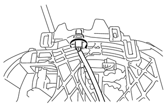
Install the indicator light wire socket.
35976
5.INSTALL NO. 2 POSITION INDICATOR SLIDE COVER
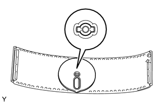
Align the cutouts on the shank of the No. 2 position indicator slide cover and the position indicator slide cover, and install the No. 2 position indicator slide cover to the position indicator slide cover.
35975
6.INSTALL POSITION INDICATOR SLIDE COVER
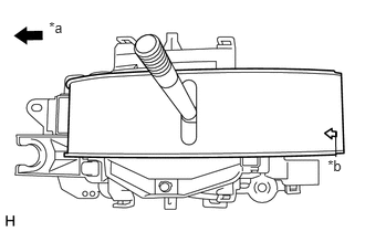
Install the position indicator slide cover to the shift lock control unit assembly.
| *a | Front of Vehicle |
| *b | Arrow |
- NOTICE:
-
Install the position indicator slide cover so that its arrow mark points to the front of the vehicle.
85903
7.INSTALL SHIFT LOCK CONTROL ECU SUB-ASSEMBLY (for Separate Type Shift Lock Control ECU)
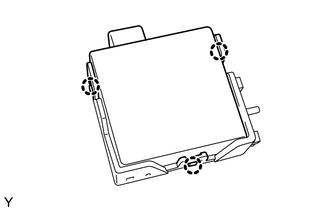
Engage the 3 claws and install the shift lock unit cover to the shift lock control ECU sub-assembly.
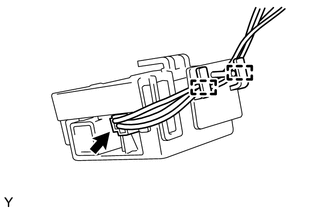
Connect the shift lock solenoid connector.
Engage the 2 clamps and install the shift lock solenoid wire to the shift lock unit cover.
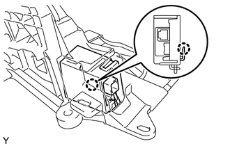
Engage the claw and install the shift lock control ECU sub-assembly to the shift lock control unit assembly.
35921
8.INSTALL CONTROL POSITION INDICATOR PLATE
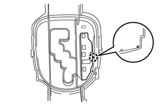
Engage the claw and install the control position indicator plate to the upper position indicator housing.
35971E
9.INSTALL UPPER POSITION INDICATOR HOUSING
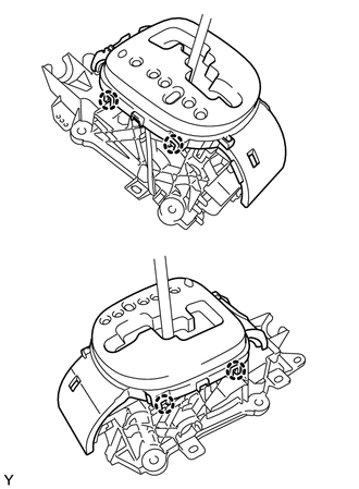
Engage the 4 claws and install the upper position indicator housing to the shift lock control unit assembly.
- NOTICE:
-
Securely engage the 4 claws.