STEERING GEAR / LINKAGE STEERING GEAR DISASSEMBLY
PROCEDURE

 45510
1.SECURE STEERING GEAR ASSEMBLY
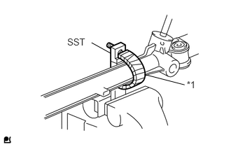
Using SST, secure the steering gear in a vise.
| *1 | Protective Tape |
- SST
- 09612-00012
- HINT:
-
Tape SST before use.
45047
2.REMOVE TIE ROD END SUB-ASSEMBLY LH
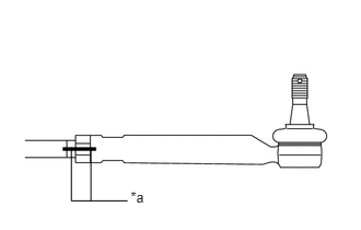
Put matchmarks on the tie rod end sub-assembly LH and steering gear.
| *a | Matchmark |
Remove the tie rod end sub-assembly LH and lock nut.
45046
3.REMOVE TIE ROD END SUB-ASSEMBLY RH
- HINT:
-
Use the same procedure for the RH side as for the LH side.
45535B
4.REMOVE STEERING RACK BOOT CLIP (for LH Side)
Using pliers, remove the steering rack boot clip.
45535B
5.REMOVE STEERING RACK BOOT CLIP (for RH Side)
- HINT:
-
Use the same procedure for the RH side as for the LH side.
45536A
6.REMOVE NO. 2 STEERING RACK BOOT CLAMP
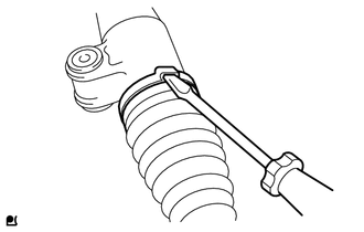
Using a screwdriver, remove the steering rack boot clamp.
45535D
7.REMOVE NO. 1 STEERING RACK BOOT CLAMP
- HINT:
-
Use the same procedure for the RH side as for the LH side.
45536
8.REMOVE NO. 2 STEERING RACK BOOT
45535
9.REMOVE NO. 1 STEERING RACK BOOT