Home › Audio / Visual / Telematics › NAVIGATION / MULTI INFO DISPLAY › NAVIGATION SYSTEM › from 2014.07
RM19S0E _56 Audio / Visual / Telematics _051484 NAVIGATION / MULTI INFO DISPLAY _0248277 NAVIGATION SYSTEM J

NAVIGATION / MULTI INFO DISPLAY  NAVIGATION SYSTEM  Steering Pad Switch Circuit  


DESCRIPTION

This circuit sends an operation signal from the steering pad switch assembly to the navigation receiver assembly.

If there is an open in the circuit, the audio system cannot be operated using the steering pad switch assembly.

If there is a short in the circuit, the same condition as when a switch is continuously depressed occurs.

Therefore, the navigation receiver assembly cannot be operated using the steering pad switch assembly, and also the navigation receiver assembly itself cannot function.

WIRING DIAGRAM
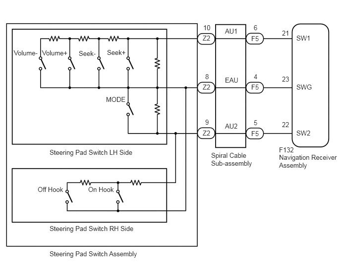
B378026E04
0.292,1.031 0.896,1.26 0.604,0.229 10 false Volume- 0.885,1.031 1.49,1.26 0.604,0.229 10 false Volume+ 1.656,1.042 2.125,1.271 0.469,0.229 10 false Seek- 2.25,1.021 2.719,1.25 0.469,0.229 10 false Seek+ 2.229,2.01 2.76,2.24 0.531,0.229 10 false MODE 0.792,3.906 1.438,4.135 0.646,0.229 10 false Off Hook 1.854,3.906 2.5,4.135 0.646,0.229 10 false On Hook 1.042,3.125 2.948,3.354 1.906,0.229 10 false Steering Pad Switch LH Side 1.042,4.729 2.948,4.958 1.906,0.229 10 false Steering Pad Switch RH Side 1.042,5.26 3.042,5.49 2,0.229 10 false Steering Pad Switch Assembly 4.729,0.573 5.083,0.802 0.354,0.229 10 false AU1 6.229,0.719 6.583,0.948 0.354,0.229 10 false SW1 6.229,1.75 6.635,1.979 0.406,0.229 10 false SWG 6.229,2.719 6.583,2.948 0.354,0.229 10 false SW2 4.729,2.573 5.083,2.802 0.354,0.229 10 false AU2 4.729,1.604 5.083,1.833 0.354,0.229 10 false EAU 4.271,0.5 4.49,0.688 0.219,0.188 10 false 10 5.927,0.615 6.156,0.802 0.229,0.188 10 false 21 5.927,1.583 6.156,1.771 0.229,0.188 10 false 23 5.927,2.542 6.156,2.729 0.229,0.188 10 false 22 4.313,1.531 4.531,1.719 0.219,0.188 10 false 8 5.333,1.531 5.552,1.719 0.219,0.188 10 false 4 5.333,0.5 5.552,0.688 0.219,0.188 10 false 6 5.333,2.5 5.552,2.688 0.219,0.188 10 false 5 4.313,2.49 4.531,2.677 0.219,0.188 10 false 9 4.26,0.719 4.531,0.906 0.271,0.188 10 false Z2 5.281,0.729 5.552,0.917 0.271,0.188 10 false F5 5.281,1.75 5.552,1.938 0.271,0.188 10 false F5 5.281,2.729 5.552,2.917 0.271,0.188 10 false F5 5.865,3.073 6.26,3.26 0.396,0.188 10 false F132 5.865,3.229 7.156,3.615 1.292,0.385 10 false Navigation Receiver Assembly 4.438,3.188 5.396,3.594 0.958,0.406 10 false Spiral Cable Sub-assembly 4.26,1.75 4.531,1.938 0.271,0.188 10 false Z2 4.26,2.719 4.531,2.906 0.271,0.188 10 false Z2

CAUTION / NOTICE / HINT

NOTICE:
·

The vehicle is equipped with a Supplemental Restraint System (SRS) which includes components such as airbags. Before servicing (including removal or installation of parts), be sure to read the precaution for Supplemental Restraint System (See page Vehicle Interior>SUPPLEMENTAL RESTRAINT SYSTEMS>AIRBAG SYSTEM(w/ VSC/Separate Type Yaw Rate Sensor)>PRECAUTION).

·

Check that the wire harness is properly installed and does not have any sharp bends, pinching or loose connections (See page General>INTRODUCTION>HOW TO TROUBLESHOOT ECU CONTROLLED SYSTEMS>ELECTRONIC CIRCUIT INSPECTION PROCEDURE).


PROCEDURE

1.INSPECT STEERING PAD SWITCH ASSEMBLY
a.

Remove the steering pad switch assembly (See page Audio / Visual / Telematics>AUDIO / VIDEO>STEERING PAD SWITCH>REMOVAL).


b.

Inspect the steering pad switch assembly (See page Audio / Visual / Telematics>AUDIO / VIDEO>STEERING PAD SWITCH>INSPECTION).


OK

2.INSPECT SPIRAL CABLE SUB-ASSEMBLY

NG

REPLACE STEERING PAD SWITCH ASSEMBLY

2.INSPECT SPIRAL CABLE SUB-ASSEMBLY
a.

Remove the spiral cable sub-assembly (See page Vehicle Interior>SUPPLEMENTAL RESTRAINT SYSTEMS>SPIRAL CABLE>REMOVAL).


b.

Inspect the spiral cable sub-assembly (See page Vehicle Interior>SUPPLEMENTAL RESTRAINT SYSTEMS>SPIRAL CABLE>INSPECTION).


OK

3.CHECK HARNESS AND CONNECTOR (NAVIGATION RECEIVER ASSEMBLY - SPIRAL CABLE SUB-ASSEMBLY)

NG

REPLACE SPIRAL CABLE SUB-ASSEMBLY

3.CHECK HARNESS AND CONNECTOR (NAVIGATION RECEIVER ASSEMBLY - SPIRAL CABLE SUB-ASSEMBLY)
a.

Disconnect the F132 navigation receiver assembly connector.


b.

Disconnect the F5 spiral cable sub-assembly connector.


c.

Measure the resistance according to the value(s) in the table below.

Standard Resistance::
Tester Connection Condition Specified Condition
F132-21 (SW1) - F5-6 (AU1) Always Below 1 Ω
F132-22 (SW2) - F5-5 (AU2) Always Below 1 Ω
F132-23 (SWG) - F5-4 (EAU) Always Below 1 Ω
F132-21 (SW1) - Body ground Always 10 kΩ or higher
F132-22 (SW2) - Body ground Always 10 kΩ or higher
F132-23 (SWG) - Body ground Always 10 kΩ or higher


OK

PROCEED TO NEXT SUSPECTED AREA SHOWN IN PROBLEM SYMPTOMS TABLE

NG

REPAIR OR REPLACE HARNESS OR CONNECTOR