Home › Power Source / Network › 1NZ-FE BATTERY / CHARGING › GENERATOR › 2011.08–2014.07
RM19S0E _57 Power Source / Network _051486 1NZ-FE BATTERY / CHARGING _0248281 GENERATOR A

1NZ-FE BATTERY / CHARGING  GENERATOR  DISASSEMBLY  


PROCEDURE

Hide 27411 1.REMOVE GENERATOR PULLEY

A193553E06
2.802,0.719 2.49,1.208 true 3.052,0.583 3.094,1.531 true 1.219,1.469 1.406,1.646 0.188,0.177 10 true *b 1.813,1.865 2,2.052 0.188,0.188 10 false *a 2.198,1.229 2.771,1.396 0.573,0.167 10 false SST1-B 2.792,1.563 3.333,1.74 0.542,0.177 10 false SST1-A

a.

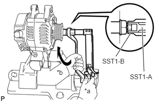
Clamp the generator housing stay in a vise tightly.


b.

Hold SST1-A with a torque wrench, and tighten SST1-B clockwise to the specified torque.

SST
09820-63011  (09820-06010, 09820-06021)

Torque:
64 N*m (653 kgf*cm, 47 ft.*lbf)

Text in Illustration
*a Hold
*b Turn

NOTICE:

Check that SST is securely fitted onto the generator rotor shaft.


c.
A193554E06
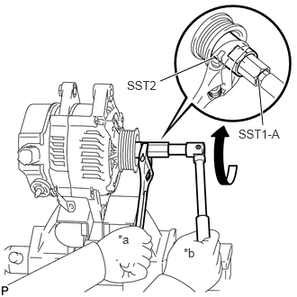
2.51,0.469 2.646,0.885 false 2.104,0.396 2.531,0.615 0.427,0.219 10 false SST2

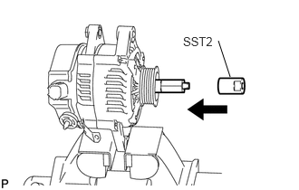
Insert SST2, and engage SST2 to the generator pulley nut.

d.
A193555E05
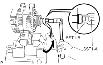
2.479,0.667 1.854,0.938 true 2.99,0.917 3.042,1.448 true 1.469,0.906 1.875,1.063 0.406,0.156 10 false SST2 2.76,1.469 3.313,1.688 0.552,0.219 10 false SST1-A 1.365,2.688 1.646,3.042 0.281,0.354 10 true *a 2.125,2.844 2.385,3.052 0.26,0.208 10 false *b

To loosen the generator pulley nut, turn SST1-A in the direction shown in the illustration.

Text in Illustration
*a Hold
*b Turn

NOTICE:

To prevent damage to the rotor shaft, do not loosen the generator pulley nut by more than one half turn.


e.

Remove SST2 from the generator assembly.

f.
A193556E09
3.052,0.635 3.083,1.542 true 2.5,1.167 2.823,0.771 true 2.198,1.188 2.76,1.354 0.563,0.167 10 false SST1-B 2.781,1.563 3.344,1.813 0.563,0.25 10 true SST1-A 2.083,1.542 2.375,1.813 0.292,0.271 10 true *a 1.427,1.385 1.625,1.594 0.198,0.208 10 true *b

Hold SST1-A, turn SST1-B, and remove SST1-A and SST1-B in the direction shown in the illustration.

Text in Illustration
*a Hold
*b Turn


g.

Remove the generator pulley nut and generator pulley.


h.

Remove the generator assembly from a vise.


Hide 27370 2.REMOVE GENERATOR BRUSH HOLDER ASSEMBLY
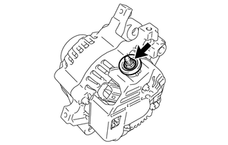
A245754

a.

Remove the nut and generator terminal insulator.

b.
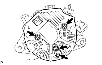
A206812E04
1.823,1.771 1.104,2.021 true 0.917,1.948 1.073,2.125 0.156,0.177 10 false *1 2.302,1.469 2.458,1.688 0.156,0.219 10 true A 2.115,0.5 2.25,0.698 0.135,0.198 10 true B 0.938,0.833 1.115,1.01 0.177,0.177 10 false B

Remove the nut A, screw and rectifier plate.

Text in Illustration
*1 Rectifier Plate


c.

Remove the 2 nuts B, and the generator rear end cover.

d.
A117359E04
2.052,1.865 2.49,1.667 true 2.5,0.875 1.854,0.5 true 2.521,0.313 1.917,0.167 true 1.719,0.073 1.875,0.25 0.156,0.177 10 false *1 1.667,0.385 1.823,0.563 0.156,0.177 10 false *2 1.865,1.823 2.042,2.031 0.177,0.208 10 true *3

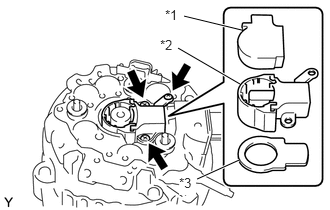
Remove the generator brush cover.


e.

Remove the 3 screws and the generator brush holder assembly.


f.

Remove the generator plate seal.

Text in Illustration
*1 Generator Brush Cover
*2 Generator Brush Holder Assembly
*3 Generator Plate Seal


Hide 27700A 3.REMOVE GENERATOR REGULATOR ASSEMBLY
A219752

a.

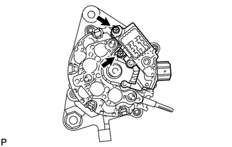
Remove the 2 screws and generator regulator assembly.


Hide 27357 4.REMOVE GENERATOR HOLDER WITH RECTIFIER
A219753

a.

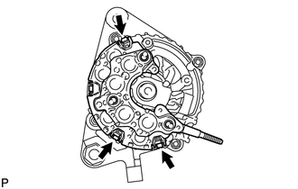
Remove the 3 screws and generator holder with rectifier.


Hide 27330 5.REMOVE GENERATOR ROTOR ASSEMBLY
A183136E03
1.865,3 2,2.885 false 1.594,1.167 2.229,0.583 2.229,0.583 1.958,2.333 true 1.438,2.271 2.219,0.594 true 2.188,0.396 2.344,0.573 0.156,0.177 10 false *1 1.708,3 1.865,3.177 0.156,0.177 10 false *2 0.927,0.76 1.083,0.938 0.156,0.177 10 false A 2.719,1.052 2.875,1.229 0.156,0.177 10 false A 2.458,2.688 2.615,2.865 0.156,0.177 10 false B 0.594,2.292 0.75,2.469 0.156,0.177 10 false A

a.

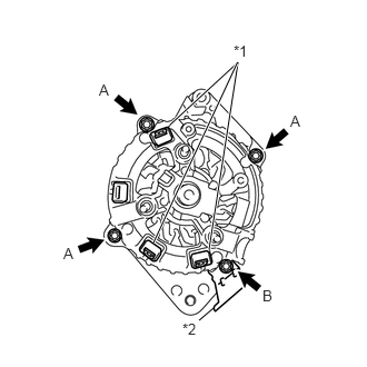
Remove the 3 terminal insulators from the generator rectifier end frame.


b.

Remove the 3 nuts A, nut B and cord clip.

Text in Illustration
*1 Terminal Insulator
*2 Cord Clip


c.
A234485E02
1.406,1.833 0.938,1.667 false 1.021,3.208 1.375,3.052 false 0.552,2.74 0.708,2.917 0.156,0.177 10 false *a 2.396,1.635 2.552,1.813 0.156,0.177 10 false *b 0.865,3.146 1.021,3.323 0.156,0.177 10 false *1 0.646,1.583 0.938,1.76 0.292,0.177 10 false SST

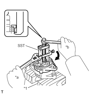
Using SST, remove the generator rectifier end frame.

SST
09286-46011  

Text in Illustration
*1 Wooden Block
*a Hold
*b Turn


d.
A247898

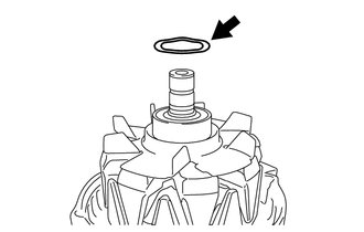
Remove the generator washer from the generator rotor assembly.
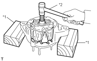

e.
A182584E04
0.24,0.615 0.5,0.813 false 2.719,1.531 3.021,1.531 false 1.75,0.323 2.031,0.177 false 0.094,0.521 0.333,0.76 0.24,0.24 10 false *1 3.031,1.438 3.271,1.677 0.24,0.24 10 false *1 2.083,0.083 2.24,0.26 0.156,0.177 10 false *2

Using a plastic hammer, remove the generator rotor assembly from the generator drive end frame assembly.

Text in Illustration
*1 Wooden Block
*2 Plastic Hammer

NOTICE:

Do not drop the generator rotor assembly.


HINT:

If the generator rotor assembly is engaged too firmly, gentry tap the generator shaft to remove it using a plastic hammer.