NETWORKING CAN COMMUNICATION SYSTEM(for Separate Type Yaw Rate Sensor) TERMINALS OF ECU
- HINT:
-
Operating the ignition switch, any switches or any doors triggers related ECU and sensor communication with the CAN, which causes resistance variation.
DISCONNECT CABLE FROM NEGATIVE BATTERY TERMINAL
Disconnect the cable from the negative (-) battery terminal before measuring the resistances of the main wire and branch wire.
- CAUTION:
-
Wait at least 90 seconds after disconnecting the cable from the negative (-) battery terminal to disable the SRS system.
- NOTICE:
- ·
Before measuring the resistance, leave the vehicle for at least 1 minute and do not operate the ignition switch, any switches or any doors. If doors need to be opened in order to check connectors, open the doors and leave them open.
·When disconnecting the cable, some systems need to be initialized after the cable is reconnected (See page General>INTRODUCTION>REPAIR INSTRUCTION>INITIALIZATION).
JUNCTION CONNECTOR
NO. 1 JUNCTION CONNECTOR
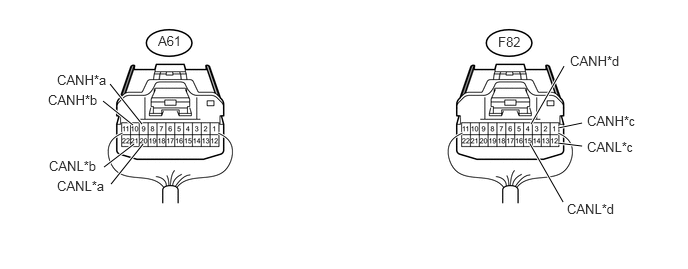
| *a | to ECM | *b | to Skid Control ECU (Brake Actuator Assembly) |
| *c | to Main Body ECU (Multiplex Network Body ECU) | *d | to No. 2 Junction Connector |
| Terminal No. (Symbol) | Wiring Color | Connect to |
|---|---|---|
| A61-9 (CANH) | L | ECM |
| A61-20 (CANL) | W | |
| A61-10 (CANH) | G | Skid Control ECU (Brake Actuator Assembly) |
| A61-21 (CANL) | W | |
| F82-1 (CANH) | R | Main Body ECU (Multiplex Network Body ECU) |
| F82-12 (CANL) | W | |
| F82-4 (CANH) | SB | No. 2 Junction Connector |
| F82-15 (CANL) | W |
NO. 2 JUNCTION CONNECTOR
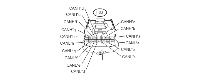
| *a | to Steering Angle Sensor (Spiral Cable Sub-assembly) | *b | to Airbag Sensor Assembly |
| *c | to Power Steering ECU Assembly | *d | to Combination Meter Assembly |
| *e | to Air Conditioning Amplifier Assembly | *f | to Yaw Rate Sensor |
| *g | to No. 1 Junction Connector | *h | to DLC3 |
| Terminal No. (Symbol) | Wiring Color | Connect to |
|---|---|---|
| F83-1 (CANH) | P | Steering Angle Sensor (Spiral Cable Sub-assembly) |
| F83-12 (CANL) | W | |
| F83-4 (CANH) | B | Airbag Sensor Assembly |
| F83-15 (CANL) | W | |
| F83-6 (CANH) | LG | Power Steering ECU Assembly |
| F83-17 (CANL) | W | |
| F83-7 (CANH) | G | Combination Meter Assembly |
| F83-18 (CANL) | W | |
| F83-8 (CANH) | V | Air Conditioning Amplifier Assembly |
| F83-19 (CANL) | W | |
| F83-9 (CANH) | BE | Yaw Rate Sensor |
| F83-20 (CANL) | W | |
| F83-10 (CANH) | SB | No. 1 Junction Connector |
| F83-21 (CANL) | W | |
| F83-11 (CANH) | GR | DLC3 |
| F83-22 (CANL) | W |
CHECK DLC3
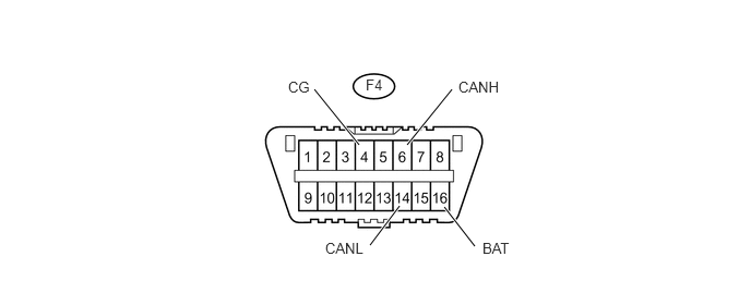
Turn the ignition switch off.
Measure the resistance according to the value(s) in the table below.
| Terminal No. (Symbol) | Wiring Color | Switch Condition | Specified Condition |
|---|---|---|---|
| F4-6 (CANH) - F4-14 (CANL) | GR - W | Ignition switch off | 54 to 69 Ω |
| F4-6 (CANH) - F4-16 (BAT) | GR - BE | Ignition switch off | 6 kΩ or higher |
| F4-14 (CANL) - F4-16 (BAT) | W - BE | Ignition switch off | 6 kΩ or higher |
| F4-6 (CANH) - F4-4 (CG) | GR - W-B | Ignition switch off | 200 Ω or higher |
| F4-14 (CANL) - F4-4 (CG) | W - W-B | Ignition switch off | 200 Ω or higher |
CHECK ECM
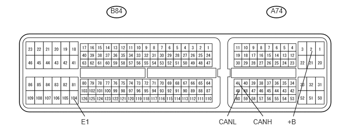
Disconnect the A74 and B84 ECM connectors.
Measure the resistance according to the value(s) in the table below.
| Terminal No. (Symbol) | Wiring Color | Switch Condition | Specified Condition |
|---|---|---|---|
| A74-41 (CANH) - A74-49 (CANL) | L - W | Ignition switch off | 108 to 132 Ω |
| A74-41 (CANH) - A74-2 (+B) | L - B | Ignition switch off | 6 kΩ or higher |
| A74-49 (CANL) - A74-2 (+B) | W - B | Ignition switch off | 6 kΩ or higher |
| A74-41 (CANH) - B84-104 (E1) | L - W-B | Ignition switch off | 200 Ω or higher |
| A74-49 (CANL) - B84-104 (E1) | W - W-B | Ignition switch off | 200 Ω or higher |
CHECK MAIN BODY ECU (MULTIPLEX NETWORK BODY ECU), INSTRUMENT PANEL JUNCTION BLOCK ASSEMBLY
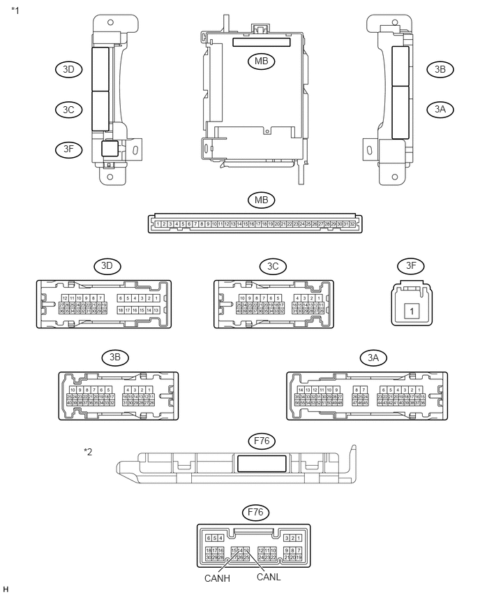
| *1 | Instrument Panel Junction Block Assembly | *2 | Main Body ECU (Multiplex Network Body ECU) |
Disconnect the F76 main body ECU (multiplex network body ECU) connector.
Disconnect the 3B and 3C instrument panel junction block assembly connectors.
Measure the resistance according to the value(s) in the table below.
| Terminal No. (Symbol) | Wiring Color | Switch Condition | Specified Condition |
|---|---|---|---|
| F76-14 (CANH) - F76-13 (CANL) | R - W | Ignition switch off | 54 to 69 Ω |
| F76-14 (CANH) - 3C-21 | R - L | Ignition switch off | 6 kΩ or higher |
| F76-13 (CANL) - 3C-21 | W - L | Ignition switch off | 6 kΩ or higher |
| F76-14 (CANH) - 3B-8 | R - W-B | Ignition switch off | 200 Ω or higher |
| F76-13 (CANL) - 3B-8 | W - W-B | Ignition switch off | 200 Ω or higher |
CHECK COMBINATION METER ASSEMBLY
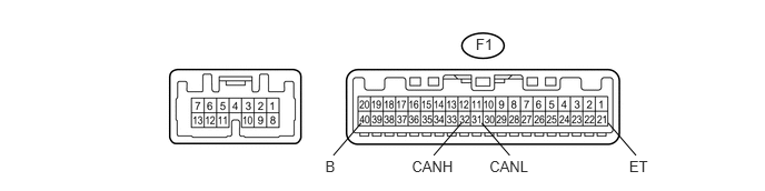
Disconnect the F1 combination meter assembly connector.
Measure the resistance according to the value(s) in the table below.
| Terminal No. (Symbol) | Wiring Color | Switch Condition | Specified Condition |
|---|---|---|---|
| F1-32 (CANH) - F1-31 (CANL) | G - W | Ignition switch off | 108 to 132 Ω |
| F1-32 (CANH) - F1-40 (B) | G - L | Ignition switch off | 6 kΩ or higher |
| F1-31 (CANL) - F1-40 (B) | W - L | Ignition switch off | 6 kΩ or higher |
| F1-32 (CANH) - F1-21 (ET) | G - W-B | Ignition switch off | 200 Ω or higher |
| F1-31 (CANL) - F1-21 (ET) | W - W-B | Ignition switch off | 200 Ω or higher |
CHECK SKID CONTROL ECU (BRAKE ACTUATOR ASSEMBLY)
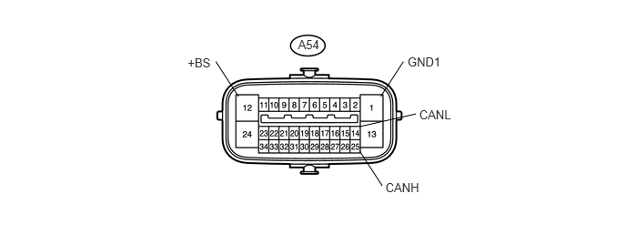
Disconnect the A54 skid control ECU (brake actuator assembly) connector.
Measure the resistance according to the value(s) in the table below.
| Terminal No. (Symbol) | Wiring Color | Switch Condition | Specified Condition |
|---|---|---|---|
| A54-25 (CANH) - A54-14 (CANL) | G - W | Ignition switch off | 54 to 69 Ω |
| A54-25 (CANH) - A54-12 (+BS) | G - W | Ignition switch off | 6 kΩ or higher |
| A54-14 (CANL) - A54-12 (+BS) | W - W | Ignition switch off | 6 kΩ or higher |
| A54-25 (CANH) - A54-1 (GND1) | G - W-B | Ignition switch off | 200 Ω or higher |
| A54-14 (CANL) - A54-1 (GND1) | W - W-B | Ignition switch off | 200 Ω or higher |
CHECK AIRBAG SENSOR ASSEMBLY
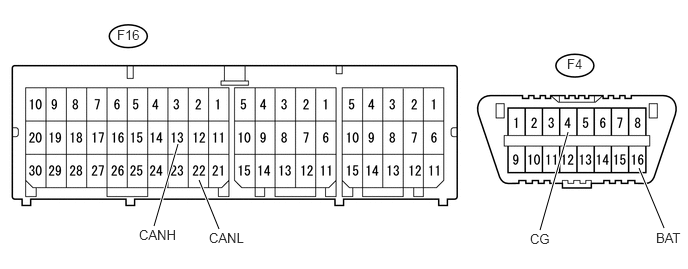
Disconnect the F16 airbag sensor assembly connector.
Measure the resistance according to the value(s) in the table below.
| Terminal No. (Symbol) | Wiring Color | Switch Condition | Specified Condition |
|---|---|---|---|
| F16-13 (CANH) - F16-22 (CANL) | B - W | Ignition switch off | 54 to 69 Ω |
| F16-13 (CANH) - F4-16 (BAT) | B - BE | Ignition switch off | 6 kΩ or higher |
| F16-22 (CANL) - F4-16 (BAT) | W - BE | Ignition switch off | 6 kΩ or higher |
| F16-13 (CANH) - F4-4 (CG) | B - W-B | Ignition switch off | 200 Ω or higher |
| F16-22 (CANL) - F4-4 (CG) | W - W-B | Ignition switch off | 200 Ω or higher |
CHECK STEERING ANGLE SENSOR (SPIRAL CABLE SUB-ASSEMBLY)
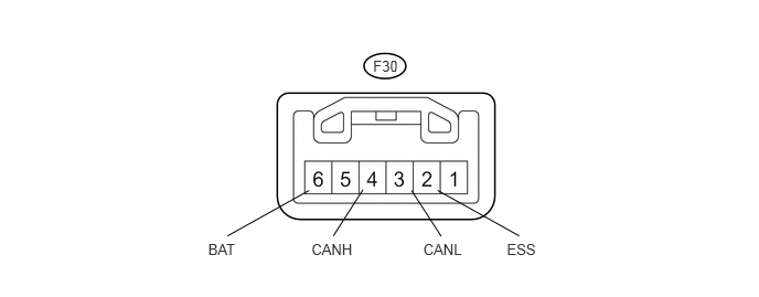
Disconnect the F30 steering angle sensor (spiral cable sub-assembly) connector.
Measure the resistance according to the value(s) in the table below.
| Terminal No. (Symbol) | Wiring Color | Switch Condition | Specified Condition |
|---|---|---|---|
| F30-4 (CANH) - F30-3 (CANL) | P - W | Ignition switch off | 54 to 69 Ω |
| F30-4 (CANH) - F30-6 (BAT) | P - SB | Ignition switch off | 6 kΩ or higher |
| F30-3 (CANL) - F30-6 (BAT) | W - SB | Ignition switch off | 6 kΩ or higher |
| F30-4 (CANH) - F30-2 (ESS) | P - BR | Ignition switch off | 200 Ω or higher |
| F30-3 (CANL) - F30-2 (ESS) | W - BR | Ignition switch off | 200 Ω or higher |
CHECK POWER STEERING ECU ASSEMBLY
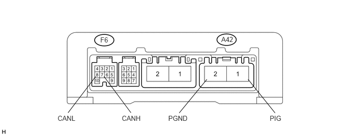
Disconnect the A42 and F6 power steering ECU assembly connectors.
Measure the resistance according to the value(s) in the table below.
| Terminal No. (Symbol) | Wiring Color | Switch Condition | Specified Condition |
|---|---|---|---|
| F6-7 (CANH) - F6-8 (CANL) | LG - W | Ignition switch off | 54 to 69 Ω |
| F6-7 (CANH) - A42-1 (PIG) | LG - W | Ignition switch off | 6 kΩ or higher |
| F6-8 (CANL) - A42-1 (PIG) | W - W | Ignition switch off | 6 kΩ or higher |
| F6-7 (CANH) - A42-2 (PGND) | LG - W-B | Ignition switch off | 200 Ω or higher |
| F6-8 (CANL) - A42-2 (PGND) | W - W-B | Ignition switch off | 200 Ω or higher |
CHECK AIR CONDITIONING AMPLIFIER ASSEMBLY
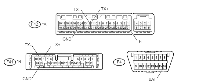
| *A | for Automatic Air Conditioning System | *B | for Manual Air Conditioning System |
Disconnect the F42*1 or F41*2 air conditioning amplifier assembly connector.
Measure the resistance according to the value(s) in the table below.
| Terminal No. (Symbol) | Wiring Color | Switch Condition | Specified Condition |
|---|---|---|---|
| F42-11 (TX+) - F42-12 (TX-)*1
F41-8 (TX+) - F41-9 (TX-)*2 |
V - W | Ignition switch off | 54 to 69 Ω |
| F42-11 (TX+) - F42-21 (B)*1
F41-8 (TX+) - F4-16 (BAT)*2 |
V - BE | Ignition switch off | 6 kΩ or higher |
| F42-12 (TX-) - F42-21 (B)*1
F41-9 (TX-) - F4-16 (BAT)*2 |
W - BE | Ignition switch off | 6 kΩ or higher |
| F42-11 (TX+) - F42-14 (GND)*1
F41-8 (TX+) - F41-23 (GND)*2 |
V - W-B | Ignition switch off | 200 Ω or higher |
| F42-12 (TX-) - F42-14 (GND)*1
F41-9 (TX-) - F41-23 (GND)*2 |
W - W-B | Ignition switch off | 200 Ω or higher |
*1: for Automatic Air Conditioning System
*2: for Manual Air Conditioning System
CHECK YAW RATE SENSOR
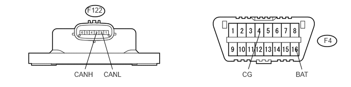
Disconnect the F122 yaw rate sensor connector.
Measure the resistance according to the value(s) in the table below.
| Terminal No. (Symbol) | Wiring Color | Switch Condition | Specified Condition |
|---|---|---|---|
| F122-3 (CANH) - F122-2 (CANL) | BE - W | Ignition switch off | 54 to 69 Ω |
| F122-3 (CANH) - F4-16 (BAT) | BE - BE | Ignition switch off | 6 kΩ or higher |
| F122-2 (CANL) - F4-16 (BAT) | W - BE | Ignition switch off | 6 kΩ or higher |
| F122-3 (CANH) - F4-4 (CG) | BE - W-B | Ignition switch off | 200 Ω or higher |
| F122-2 (CANL) - F4-4 (CG) | W - W-B | Ignition switch off | 200 Ω or higher |