RM19S0E
_58
Vehicle Interior
_051498
HEATING / AIR CONDITIONING
_0248350
AIR CONDITIONING SYSTEM(for Automatic Air Conditioning System)
U
HEATING / AIR CONDITIONING AIR CONDITIONING SYSTEM(for Automatic Air Conditioning System) TERMINALS OF ECU
CHECK AIR CONDITIONING AMPLIFIER ASSEMBLY

3.385,0.26 3.646,0.438
0.26,0.177
10
false
F42
5.021,0.26 5.188,0.438
0.167,0.177
10
false
z4
- HINT:
-
Check from the rear of the connector while it is connected to the air conditioning amplifier assembly.
| Terminal No. (Symbol) | Wiring Color | Terminal Description | Condition | Specified Condition |
|---|---|---|---|---|
| F42-1 (IG+) - F42-14 (GND) | V - W-B | Ignition power supply | Ignition switch: ON | 11 to 14 V |
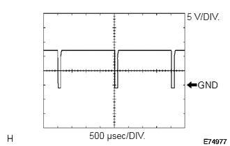
| F42-2 (SOL+) - F42-14 (GND) | P - W-B | A/C compressor operation signal | Engine idling | Pulse generation
(See waveform 1) |
| Blower switch: LO | ||||
| A/C switch: ON | ||||
| F42-5 (TAM) - F42-13 (SG-2) | W - L | A/C ambient temperature sensor signal | Ignition switch ON at 25°C (77°F) | 1.35 to 1.75 V |
| F42-9 (PRE) - F42-14 (GND) | GR - W-B | Air conditioning pressure sensor signal | Refrigerant pressure: Normal | 0.63 to 4.73 V |
| Refrigerant pressure: Abnormal (less than 0.176 MPaG [1.8 kgf/cm2]) or more than 3.03 MPaG [31 kgf/cm2]) | Below 0.63 V or 4.73 V or more | |||
| F42-10 (S5-3) - F42-14 (GND) | Y - W-B | Power supply for pressure sensor | Ignition switch: ON | 4.75 to 5.25 V |
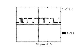
| F42-11 (TX+) - F42-14 (GND) | V - W-B | CAN communication signal | Ignition switch: ON | Pulse generation
(See waveform 2) |
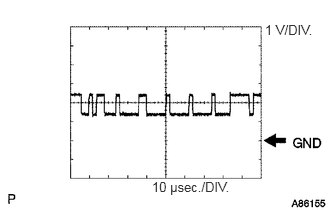
| F42-12 (TX-) - F42-14 (GND) | W - W-B | CAN communication signal | Ignition switch: ON | Pulse generation
(See waveform 3) |
| F42-13 (SG-2) - Body ground | L - Body ground | Ground for ambient temperature sensor and A/C pressure sensor | Always | Below 1 Ω |
| F42-14 (GND) - Body ground | W-B - Body ground | Ground for main power supply | Always | Below 1 Ω |
| F42-21 (B) - F42-14 (GND) | BE - W-B | Battery power supply | Always | 11 to 14 V |
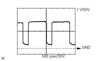
| F42-22 (BLW) - F42-14 (GND) | R - W-B | Blower motor control signal | Ignition switch: ON | Pulse generation
(See waveform 4) |
| Blower switch: LO | ||||
| F42-29 (TR) - F42-34 (SG-1) | P - SB | Room temperature sensor signal | Ignition switch: ON | 1.8 to 2.2 V |
| Vehicle interior temperature: 25°C | ||||
| F42-33 (TSD) - F42-14 (GND) | R - W-B | Solar sensor signal | Ignition switch: ON | 0.8 to 4.3 V |
| Solar sensor subject to electric light | ||||
| F42-34 (SG-1) - Body ground | SB - Body ground | Ground for room temperature sensor | Always | Below 1 Ω |
| F42-37 (LIN1) - F42-14 (GND) | LG - W-B | LIN communication signal | Ignition switch: ON | Pulse generation |
| z4-2 (BUSG) - Body ground | - | Ground for BUS IC | Always | Below 1 Ω |
| z4-3 (BUS) - z4-2 (BUSG) | - | BUS IC control signal | Ignition switch: ON | Pulse generation |
| z4-4 (BBUS) - z4-2 (BUSG) | - | BUS IC power supply | Always | 11 to 14 V |
| z4-5 (SGA) - Body ground | - | Ground for evaporator temperature sensor | Always | Below 1 Ω |
| z4-6 (TEA) - z4-5 (SGA) | - | Evaporator temperature sensor signal | Ignition switch: ON | 1.4 to 1.8 V |
| Evaporator temperature: 15°C (59°F) |
If the result is not as specified, there may be a malfunction in the wire harness.
a.
2.792,0.167 3.333,0.365
0.542,0.198
10
false
5 V/DIV.
1.333,1.948 2.313,2.115
0.979,0.167
10
false
500 μsec/DIV.
Waveform 1: Using an oscilloscope
| Terminal Name | F42-2 (SOL+) - F42-14 (GND) |
| Tester Range | 5 V/DIV, 500 μs/DIV |
| Condition | Engine idling
Blower switch LO A/C switch ON |
b.
2.771,0.323 3.313,0.51
0.542,0.188
10
false
1 V/DIV.
3,1.385 3.333,1.563
0.333,0.177
10
false
GND
1.594,1.885 2.469,2.073
0.875,0.188
10
false
10 μsec/DIV.
Waveform 2 (Reference) : Using an oscilloscope
| Terminal Name | F42-11 (TX+) - F42-14 (GND) |
| Tester Range | 1 V/DIV, 10 μs/DIV |
| Condition | Ignition switch ON |
- HINT:
-
The waveform varies depending on the CAN communication signal.
c.
2.76,0.229 3.292,0.406
0.531,0.177
10
false
1 V/DIV.
1.583,1.865 2.5,2.042
0.917,0.177
10
false
10 μsec./DIV.
Waveform 3 (Reference) : Using an oscilloscope
| Terminal Name | F42-12 (TX-) - F42-14 (GND) |
| Tester Range | 1 V/DIV, 10 μs/DIV |
| Condition | Ignition switch ON |
- HINT:
-
The waveform varies depending on the CAN communication signal.
d.
2.931,1.611 3.356,1.792
0.425,0.181
10
GND
2.737,0.259 3.287,0.456
0.549,0.198
10
1 V/DIV.
1.5,1.926 2.461,2.100
0.961,0.174
10
500 μsec/DIV.
Waveform 4: Using an oscilloscope.
| Terminal Name | F42-22 (BLW) - F42-14 (GND) |
| Tester Range | 1 V/DIV, 500 μs/DIV |
| Condition | Ignition switch ON
Blower switch LO |
- HINT:
-
When the blower level is increased, the duty ratio changes accordingly.
CHECK AIR CONDITIONING CONTROL ASSEMBLY

3.417,0.281 3.708,0.438
0.292,0.156
10
false
F40
| Terminal No. (Symbol) | Wiring Color | Terminal Description | Condition | Specified Condition |
|---|---|---|---|---|
| F40-5 (IG+) - F40-8 (GND) | V - BR | Ignition power supply | Ignition switch: ON | 11 to 14 V |
| F40-3 (LIN1) - F40-8 (GND) | LG - BR | LIN communication signal | Ignition switch: ON | Pulse generation |
| F40-8 (GND) - Body ground | BR - Body Ground | Ground for air conditioning control assembly | Always | Below 1 Ω |
If the result is not as specified, there may be a malfunction in the wire harness.