HEATING / AIR CONDITIONING AIR CONDITIONING SYSTEM(for Automatic Air Conditioning System) DIAGNOSIS SYSTEM
DESCRIPTION
Air conditioning system data and Diagnostic Trouble Codes (DTCs) can be read through the Data Link Connector 3 (DLC3) of the vehicle. When the system seems to be malfunctioning, use the intelligent tester to check for malfunctions and perform troubleshooting.
CHECK DLC3
Check the DLC3 (See page General>INTRODUCTION>HOW TO TROUBLESHOOT ECU CONTROLLED SYSTEMS>GENERAL INFORMATION).
LIST OF OPERATION METHODS
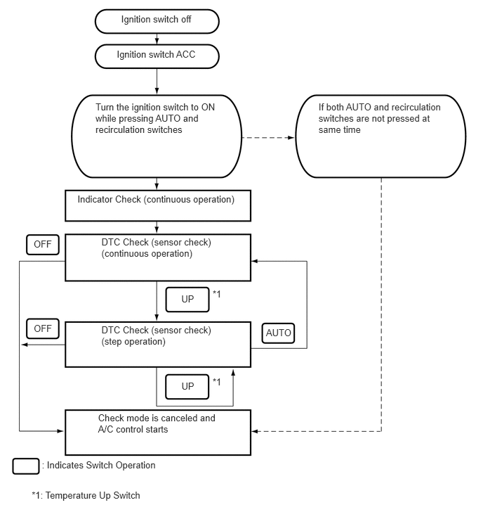
By operating each of the air conditioning control switches as shown in the diagram below, it is possible to enter diagnostic check mode.
INDICATOR CHECK
Turn the ignition switch off.
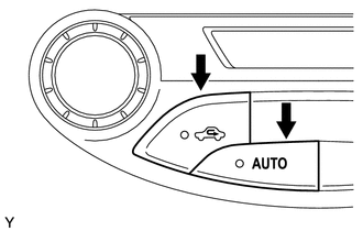
Turn the ignition switch to ON while simultaneously pressing the AUTO switch and the recirculation switch.
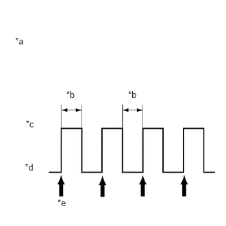
Check that all indicators and the display area are turned on and off 4 times in succession at 1-second intervals.
| *a | Blinking Pattern |
| *b | 1 second |
| *c | ON |
| *d | OFF |
| *e | 4 times |
- HINT:
-
After the indicator check is completed, the system automatically enters sensor check mode.
Press the OFF switch to terminate the panel diagnosis.
DTC CHECK (SENSOR CHECK)
Perform the indicator check.
- HINT:
-
After the indicator check is completed, the system automatically enters sensor check mode.
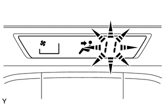
Check the sensor check results displayed on the set temperature display.
| Results | Code Display |
|---|---|
| Present malfunction | Blinks |
- HINT:
- ·
The illustration shows the display when code 11 is output.
·When two or more sensor check codes are detected, the codes are displayed in ascending numerical order.
·In cases with two or more codes, making them difficult to read, press the temperature up switch to activate the step operation and display them one by one.
·The codes are displayed in ascending numerical order as the temperature up switch is pressed.
When any sensor check codes are displayed, refer to the DTC chart (See page Vehicle Interior>HEATING / AIR CONDITIONING>AIR CONDITIONING SYSTEM (for Automatic Air Conditioning System)>DIAGNOSTIC TROUBLE CODE CHART).
Press the OFF switch to terminate the panel diagnosis.
PANEL DIAGNOSIS (CLEAR SENSOR CHECK CODE)
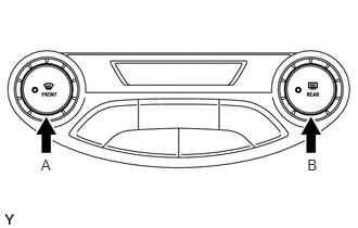
Inspect, and repair or replace the malfunctioning parts.
Clear the sensor check codes.
While pressing the DEF switch during sensor check mode, press the Rr DEF switch.
Perform the sensor check and confirm that normal code 00 is displayed.