RM19S0E
_58
Vehicle Interior
_051498
HEATING / AIR CONDITIONING
_0248350
AIR CONDITIONING SYSTEM(for Automatic Air Conditioning System)
U
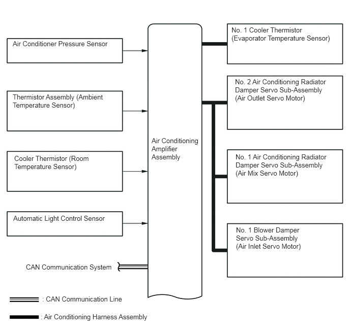
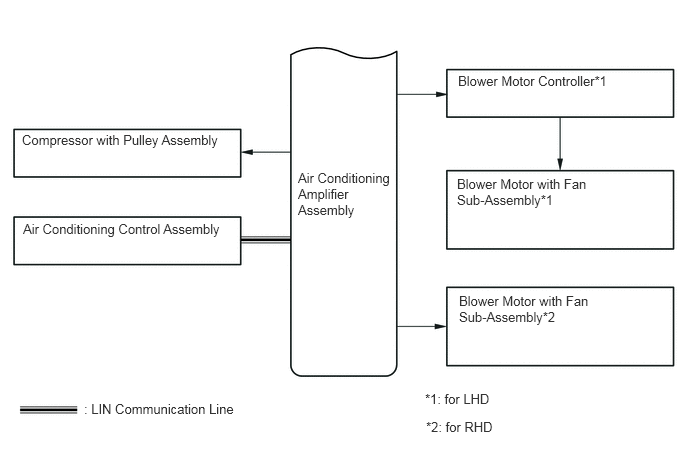
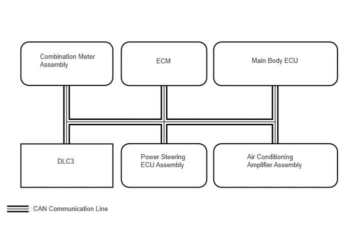
HEATING / AIR CONDITIONING AIR CONDITIONING SYSTEM(for Automatic Air Conditioning System) SYSTEM DIAGRAM
0.26,1.906 2.188,2.292
1.927,0.385
10
false
Thermistor Assembly (Ambient Temperature Sensor)
3.104,2.802 4.115,3.49
1.01,0.688
10
false
Air Conditioning Amplifier Assembly
0.531,5.396 2.344,5.583
1.813,0.188
10
false
CAN Communication System
0.26,0.813 2.24,1.021
1.979,0.208
10
false
Air Conditioner Pressure Sensor
0.865,6.052 2.573,6.26
1.708,0.208
10
false
: CAN Communication Line
0.292,3.167 1.844,3.51
1.552,0.344
10
false
Cooler Thermistor (Room Temperature Sensor)
4.74,0.531 6.781,0.906
2.042,0.375
10
false
No. 1 Cooler Thermistor (Evaporator Temperature Sensor)
4.823,3.135 6.729,3.698
1.906,0.563
10
false
No. 1 Air Conditioning Radiator Damper Servo Sub-Assembly (Air Mix Servo Motor)
4.833,4.635 6.167,5.177
1.333,0.542
10
false
No. 1 Blower Damper Servo Sub-Assembly (Air Inlet Servo Motor)
4.813,1.594 6.74,2.146
1.927,0.552
10
false
No. 2 Air Conditioning Radiator Damper Servo Sub-Assembly (Air Outlet Servo Motor)
0.271,4.396 2.198,4.604
1.927,0.208
10
false
Automatic Light Control Sensor
0.833,6.417 3.094,6.625
2.26,0.208
10
false
: Air Conditioning Harness Assembly
3.104,1.771 4.115,2.458
1.01,0.688
10
false
Air Conditioning Amplifier Assembly
0.229,1.375 2.333,1.594
2.104,0.219
10
false
Compressor with Pulley Assembly
4.781,3.052 6.208,3.396
1.427,0.344
10
false
Blower Motor with Fan Sub-Assembly*2
4.771,0.76 6.354,0.979
1.583,0.219
10
false
Blower Motor Controller*1
4.76,1.833 6.188,2.177
1.427,0.344
10
false
Blower Motor with Fan Sub-Assembly*1
0.875,4.177 2.479,4.375
1.604,0.198
10
false
: LIN Communication Line
0.24,2.302 2.344,2.51
2.104,0.208
10
false
Air Conditioning Control Assembly
4.427,4.073 5.115,4.24
0.688,0.167
10
false
*1: for LHD
4.438,4.365 5.146,4.552
0.708,0.188
10
false
*2: for RHD
0.616,4.276 2.313,4.430
1.697,0.154
10
: CAN Communication Line
5.147,3.188 6.352,3.525
1.205,0.337
10
Air Conditioning Amplifier Assembly
3.255,1.183 3.593,1.342
0.338,0.160
10
ECM
1.197,3.279 1.588,3.435
0.391,0.156
10
DLC3
0.832,1.093 2.036,1.430
1.204,0.337
10
Combination Meter Assembly
2.932,3.19 3.908,3.523
0.976,0.334
10
Power Steering ECU Assembly
5.246,1.182 6.254,1.343
1.008,0.161
10
Main Body ECU
| Transmitter | Receiver | Signal | Communication Line |
|---|---|---|---|
| Air conditioning amplifier assembly | ECM | A/C compressor control signal | CAN |
| Idle up request signal | |||
| External variable control solenoid current signal | |||
| Cooling fan motor driving request signal | |||
| Ambient temperature signal | |||
| Air conditioning amplifier assembly | Air conditioning control assembly | Front panel indication signal | LIN |
| AUTO indication signal | |||
| A/C indication signal | |||
| MODE indication signal | |||
| REC indication signal | |||
| FRS indication signal | |||
| RDEF indication signal | |||
| Blower level indication signal | |||
| Set temperature indication signal | |||
| Air conditioning amplifier assembly | DLC3 | Diagnostic tool response | CAN |
| Combination meter assembly | Air conditioning amplifier assembly | Vehicle speed signal | CAN |
| Power steering ECU assembly | Air conditioning amplifier assembly | Loading control level | CAN |
| Main body ECU | Air conditioning amplifier assembly | Destination symbol steering | CAN |
| ECM | Air conditioning amplifier assembly | Engine revolution speed signal | CAN |
| Engine coolant temperature signal | |||
| A/C control cut signal | |||
| Variable control prohibition signal | |||
| Air conditioning control assembly | Air conditioning amplifier assembly | AUTO switch signal | LIN |
| OFF switch signal | |||
| A/C switch signal | |||
| DEF switch signal | |||
| MODE switch signal | |||
| RDEF switch signal | |||
| Blower switch signal (FAN+, FAN-) | |||
| Set temperature switch signal (UP, DOWN) |