Home › Vehicle Interior › HEATING / AIR CONDITIONING › AIR CONDITIONING SYSTEM (for Automatic Air Conditioning System)
RM19S0E _58 Vehicle Interior _051498 HEATING / AIR CONDITIONING _0248350 AIR CONDITIONING SYSTEM(for Automatic Air Conditioning System) C

HEATING / AIR CONDITIONING  AIR CONDITIONING SYSTEM(for Automatic Air Conditioning System)  B1497/97  BUS IC Communication Malfunction  


DESCRIPTION

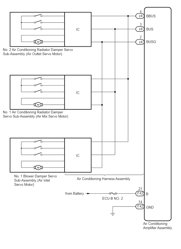
The air conditioning harness assembly connects the air conditioning amplifier assembly and each servo motor. The air conditioning amplifier assembly supplies power and sends operation instructions to each servo motor through the air conditioning harness assembly. Each servo motor sends the damper position information to the air conditioning amplifier assembly.

DTC No. DTC Detection Condition Trouble Area
B1497/97 An open circuit or malfunction in the communication line.
·

Air conditioning harness assembly

·

Harness or connector

·

Air conditioning amplifier assembly


WIRING DIAGRAM

E231122E02
3.01,1.083 3.177,1.229 0.167,0.146 10 false IC 0.115,1.885 2.969,2.385 2.854,0.5 10 false No. 2 Air Conditioning Radiator Damper Servo Sub-Assembly (Air Outlet Servo Motor) 3.01,3.594 3.177,3.74 0.167,0.146 10 false IC 3.01,6.094 3.177,6.24 0.167,0.146 10 false IC 0.115,4.365 2.844,4.896 2.729,0.531 10 false No. 1 Air Conditioning Radiator Damper Servo Sub-Assembly (Air Mix Servo Motor) 0.563,6.906 2.323,7.427 1.76,0.521 10 false No. 1 Blower Damper Servo Sub-Assembly (Air Inlet Servo Motor) 5.5,0.542 5.667,0.688 0.167,0.146 10 false z4 5.531,0.885 5.625,1.042 0.094,0.156 10 false 3 5.531,0.375 5.635,0.521 0.104,0.146 10 false 4 5.531,1.385 5.635,1.531 0.104,0.146 10 false 2 5.792,0.552 6.198,0.698 0.406,0.146 10 false BBUS 5.792,1.073 6.104,1.219 0.313,0.146 10 false BUS 5.792,1.573 6.208,1.729 0.417,0.156 10 false BUSG 5.5,1.063 5.667,1.208 0.167,0.146 10 false z4 5.5,1.583 5.667,1.729 0.167,0.146 10 false z4 3.042,7.01 5.24,7.167 2.198,0.156 10 false Air Conditioning Harness Assembly 4.052,7.792 4.927,7.938 0.875,0.146 10 false ECU-B NO. 2 2.583,7.594 3.365,7.792 0.781,0.198 10 false from Battery 5.438,7.583 5.708,7.729 0.271,0.146 10 false F42 5.479,7.406 5.656,7.552 0.177,0.146 10 false 21 5.479,7.927 5.656,8.073 0.177,0.146 10 false 14 5.781,7.615 5.917,7.771 0.135,0.156 10 false B 5.781,8.146 6.094,8.323 0.313,0.177 10 false GND 5.667,8.792 6.875,9.104 1.208,0.313 10 false Air Conditioning Amplifier Assembly 5.438,8.104 5.708,8.25 0.271,0.146 10 false F42

CAUTION / NOTICE / HINT

NOTICE:

Inspect the fuses for circuits related to this system before performing the following inspection procedure.


PROCEDURE
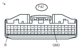
1.CHECK HARNESS AND CONNECTOR (AIR CONDITIONING AMPLIFIER ASSEMBLY - BATTERY AND BODY GROUND)
a.
U158641E01
1.599,0.2 1.855,0.381 0.256,0.181 10 F42 0.1,0.07 0.270,0.230 0.170,0.161 10 *a 0.184,1.802 0.299,1.958 0.114,0.156 10 B 2.204,1.811 2.533,1.953 0.330,0.142 10 GND 0.365,1.394 0.244,1.785 false 2.23,1.209 2.393,1.794 false

Disconnect the F42 air conditioning amplifier assembly connector.

b.

Measure the voltage according to the value(s) in the table below.

Standard Voltage:
Tester Condition Condition Specified Condition
F42-21 (B) - Body ground Always 11 to 14 V


c.

Measure the resistance according to the value(s) in the table below.

Standard Resistance:
Tester Condition Condition Specified Condition
F42-14 (GND) - Body ground Always Below 1 Ω


Text in Illustration
*a Rear view of wire harness connector
(to Air Conditioning Amplifier Assembly)


OK

2.CHECK AIR CONDITIONING AMPLIFIER ASSEMBLY

NG

REPAIR OR REPLACE HARNESS OR CONNECTOR

2.CHECK AIR CONDITIONING AMPLIFIER ASSEMBLY
a.

Reconnect the air conditioning amplifier assembly connector.


b.
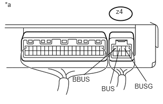
U158537E01
2.619,1.015 3.086,1.71 false 2.838,1.734 3.262,1.904 0.424,0.170 10 BUSG 2.446,0.153 2.644,0.334 0.198,0.181 10 z4 0.105,0.01 0.282,0.151 0.177,0.141 10 *a 2.525,1.015 2.326,1.757 false 2.14,1.778 2.453,1.948 0.313,0.170 10 BUS 2.443,1.015 1.768,1.575 false 1.525,1.584 1.932,1.755 0.407,0.170 10 BBUS

Remove the air conditioning amplifier assembly with its connectors still connected (See page Vehicle Interior>HEATING / AIR CONDITIONING>AIR CONDITIONING AMPLIFIER>REMOVAL).


c.

Measure the resistance according to the value(s) in the table below.

Standard Resistance:
Tester Connection Condition Specified Condition
z4-2 (BUSG) - Body ground Always Below 1 Ω


d.

Measure the voltage according to the value(s) in the table below.

Standard Voltage:
Tester Connection Switch Condition Specified Condition
z4-4 (BBUS) - z4-2 (BUSG) Ignition switch ON 11 to 14 V
z4-3 (BUS) - z4-2 (BUSG) Ignition switch ON Pulse generation


Text in Illustration
*a Component with harness connected
(Air Conditioning Amplifier Assembly)

Result
Result Proceed to
OK (When troubleshooting according to the DTC) A
OK (When troubleshooting according to Problem Symptoms Table) B
NG C


A

REPLACE AIR CONDITIONING HARNESS ASSEMBLY

B

C

REPLACE AIR CONDITIONING AMPLIFIER ASSEMBLY