RM19S0E
_58
Vehicle Interior
_051498
HEATING / AIR CONDITIONING
_0248351
AIR CONDITIONING SYSTEM(for Manual Air Conditioning System)
U
HEATING / AIR CONDITIONING AIR CONDITIONING SYSTEM(for Manual Air Conditioning System) TERMINALS OF ECU
CHECK AIR CONDITIONING AMPLIFIER ASSEMBLY (w/ Cooler)
3.469,0.229 3.729,0.406
0.26,0.177
10
false
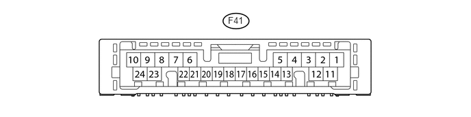
F41
- HINT:
-
Check from the rear of the connector while it is connected to the air conditioning amplifier assembly.
| Terminal No. (Symbol) | Wiring Color | Terminal Description | Condition | Specified Condition |
|---|---|---|---|---|
| F41-1 (IG+) - F41-23 (GND) | V - W-B | Ignition power supply | Ignition switch: ON | 11 to 14 V |
| F41-2 (A/C) - F41-23 (GND)*1 | G - W-B | A/C switch signal | Ignition switch: ON | Below 1 V → 11 to 14 V |
| Defroster: OFF | ||||
| A/C switch: OFF → ON | ||||
| Defroster mode detection switch signal | Ignition switch: ON | Below 1 V → 11 to 14 V | ||
| A/C switch: OFF | ||||
| Defroster: OFF → ON | ||||
| F41-3 (B/V) - F41-15 (SG- 1)*2 | SB - B | Room temperature set signal | Ignition switch: ON | 4.5 to 5.5 V → Below 1 V |
| No. 3 heater control knob: MAX COOL | ||||
| F41-4 (TE) - F41-15 (SG- 1) | GR - B | Evaporator temperature sensor signal | Ignition switch: ON | 1.0 to 1.3 V |
| Temperature near evaporator: 15°C (59°F) | ||||
| F41-5 (SG-2) - Body ground | L - Body ground | Ground for ambient temperature sensor and A/ C pressure sensor | Always | Below 1 Ω |
| F41-7 (PRE) - F41-23 (GND) | GR - W-B | A/C pressure sensor signal | Refrigerant pressure: Normal | 0.63 to 4.73 V |
| Refrigerant pressure: Abnormal
(less than 0.176 MPaG [1.8 kgf/cm2] or more than 3.03 MPaG [31 kgf/cm2]) |
Below 0.63 V or 4.73 V or more | |||
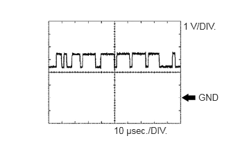
| F41-8 (TX+) - F41-23 (GND) | V - W-B | CAN communication signal | Ignition switch: ON | Pulse generation
(See waveform 1) |
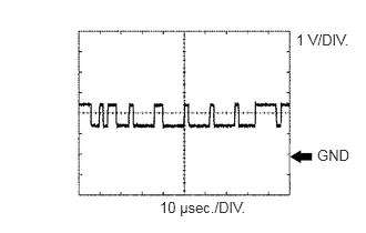
| F41-9 (TX-) - F41-23 (GND) | W - W-B | CAN communication signal | Ignition switch: ON | Pulse generation
(See waveform 2) |
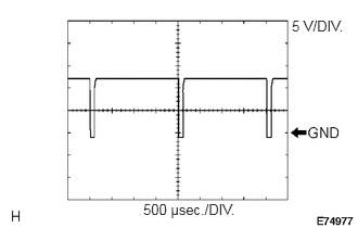
| F41-11 (SOL+) - F41-23 (GND) | P - W-B | A/C compressor operation signal | Engine idling | Pulse generation
(See waveform 3) |
| Blower switch: 1 | ||||
| A/C switch: ON*1 | ||||
| No. 3 heater control knob: MAX COOL*2 | ||||
| F41-14 (HR) - Body ground | R - Body ground | Heater blower motor relay operation signal | Ignition switch: ON | 11 to 14 V → Below 1 V |
| Blower switch: 0 → 1 | ||||
| F41-15 (SG-1) - Body ground | B - Body ground | Ground for evaporator temperature sensor | Always | Below 1 Ω |
| F41-16 (LED) - Body ground*1 | BE - Body ground | A/C switch indicator signal | Engine idling | 11 to 14 V → Below 4 V |
| A/C switch: ON | ||||
| Blower switch: 0 → 1 | ||||
| F41-17 (SBLW) - Body ground | GR - Body ground | Blower motor ON signal | Ignition switch: ON | 11 to 14 V → Below 1 V |
| Blower switch: 0 → 1 | ||||
| F41-22 (TAM) - F41-5 (SG-2) | W - L | A/C ambient temperature sensor signal | Ignition switch ON at 25°C (77°F) | 1.35 to 1.75 V |
| F41-23 (GND) - Body ground | W-B - Body ground | Ground for main power supply | Always | Below 1 Ω |
| F41-24 (S5-3) - F41-23 (GND) | Y - W-B | Power supply for pressure sensor | Ignition switch: ON | 4.75 to 5.25 V |
*1: w/ Heater
*2: w/o Heater
If the result is not as specified, there may be a malfunction in the wire harness.
a.
2.75,0.313 3.313,0.49
0.563,0.177
10
false
1 V/DIV.
2.979,1.385 3.313,1.552
0.333,0.167
10
false
GND
1.708,1.885 2.552,2.063
0.844,0.177
10
false
10 μsec./DIV.
Waveform 1 (Reference) : Using an oscilloscope
| Terminal Name | F41-8 (TX+) - F41-23 (GND) |
| Tester Range | 1 V / DIV., 10 μsec. / DIV. |
| Condition | Ignition switch ON |
- HINT:
-
The waveform varies depending on the CAN communication signal.
b.
2.781,0.292 3.313,0.469
0.531,0.177
10
false
1 V/DIV.
2.979,1.375 3.323,1.552
0.344,0.177
10
false
GND
1.5,1.865 2.365,2.042
0.865,0.177
10
false
10 μsec./DIV.
Waveform 2 (Reference) : Using an oscilloscope
| Terminal Name | F41-9 (TX-) - F41-23 (GND) |
| Tester Range | 1 V / DIV., 10 μsec. / DIV. |
| Condition | Ignition switch ON |
- HINT:
-
The waveform varies depending on the CAN communication signal.
c.
2.802,0.167 3.333,0.333
0.531,0.167
10
false
5 V/DIV.
1.375,1.927 2.438,2.094
1.063,0.167
10
false
500 μsec./DIV.
Waveform 3: Using an oscilloscope
| Terminal Name | F41-11 (SOL+) - F41-23 (GND) |
| Tester Range | 5 V / DIV., 500 μsec. / DIV. |
| Condition | Engine idling
Blower switch 1 A/C switch ON*1 No. 3 heater control knob MAX COOL*2 |
*1: w/ Heater
*2: w/o Heater
CHECK AIR CONDITIONING AMPLIFIER ASSEMBLY (w/o Cooler)
3.469,0.229 3.729,0.406
0.26,0.177
10
false
F41
- HINT:
-
Check from the rear of the connector while it is connected to the air conditioning amplifier assembly.
| Terminal No. (Symbol) | Wiring Color | Terminal Description | Condition | Specified Condition |
|---|---|---|---|---|
| F41-14 (HR) - Body ground | R - Body ground | Heater blower motor relay operation signal | Ignition switch: ON | 11 to 14 V → Below 1 V |
| Blower switch: 0 → 1 | ||||
| F41-17 (SBLW) - Body ground | GR - Body ground | Blower motor ON signal | Ignition switch: ON | 11 to 14 V → Below 1 V |
| Blower switch: 0 → 1 |