RM19S0E
_58
Vehicle Interior
_051498
HEATING / AIR CONDITIONING
_0248364
SOLAR SENSOR
G
HEATING / AIR CONDITIONING SOLAR SENSOR INSPECTION
PROCEDURE

 89120A
1.INSPECT SOLAR SENSOR (AUTOMATIC LIGHT CONTROL SENSOR)
a.
0.588,1.045 0.844,1.226
0.256,0.181
10
F73
0.071,0.043 0.241,0.203
0.170,0.161
10
*a
0.681,0.573 1.059,0.720
0.378,0.147
10
CLTB
2.288,1.392 2.671,1.548
0.383,0.156
10
CLTE
1.563,1.171 1.128,0.653
false
1.871,1.336 2.268,1.478
false
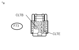
Disconnect the F73 solar sensor connector.
| *a | Front view of wire harness connector
(to Solar Sensor) |
b.
Measure the voltage according to the value(s) in the table below.
- Standard Voltage:
Tester Connection Switch Condition Specified Condition F73-3 (CLTB) - F73-5 (CLTE) Ignition switch off Below 1 V F73-3 (CLTB) - F73-5 (CLTE) Ignition switch ON 11 to 14 V
c.
Reconnect the solar sensor connector.
d.
Turn the ignition switch to ON.
e.
0.588,0.865 0.845,1.046
0.256,0.181
10
F73
0.067,0.071 0.237,0.231
0.170,0.161
10
*a
0.488,1.384 0.873,1.540
0.385,0.156
10
CLTE
2.504,0.654 2.819,0.810
0.316,0.156
10
TSD
2.465,0.74 1.932,0.873
false
0.944,1.466 1.507,1.294
false
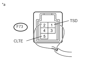
Measure the voltage according to the value(s) in the table below.
| *a | Component with harness connected
(Solar Sensor) |
- Standard Voltage:
Tester Connection Condition Specified Condition F73-1(TSD) - F73-5(CLTE) Without direct light exposure (Sensor covered) Below 0.8 V F73-1(TSD) - F73-5(CLTE) When exposed to sunlight or an inspection light 4.0 to 4.6 V
- NOTICE:
-
Use an incandescent light for inspection. Bring it within about 30 cm (11.8 in.) of the solar sensor.
If the result is not as specified, replace the solar sensor.