WIPER / WASHER WIPER SWITCH INSPECTION
PROCEDURE

 84650
1.INSPECT WINDSHIELD WIPER SWITCH ASSEMBLY (for LHD)
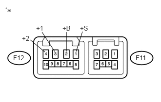
Check the front wiper switch.
| *a | Component without harness connected
(Windshield Wiper Switch Assembly) |
Measure the resistance according to the value(s) in the table below.
- Standard Resistance:
Front Wiper Switch Tester Connection Switch Condition Specified Condition F12-1 (+S) - F12-3 (+1) OFF Below 1 Ω INT F12-2 (+B) - F12-3 (+1) MIST LO F12-2 (+B) - F12-4 (+2) HI
If the result is not as specified, replace the wiper switch.
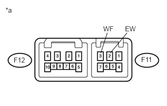
Check the front washer switch.
| *a | Component without harness connected
(Windshield Wiper Switch Assembly) |
Measure the resistance according to the value(s) in the table below.
- Standard Resistance:
Front Washer Switch Tester Connection Switch Condition Specified Condition F11-2 (EW) - F11-3 (WF) ON Below 1 Ω OFF 10 kΩ or higher
If the result is not as specified, replace the wiper switch.
Check the intermittent operation.
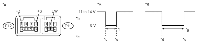
| *A | FAST: Connect battery negative lead to terminal F12-1 (+S) | *B | SLOW: Connect battery negative lead to terminal F12-1 (+S) |
| *a | Component without harness connected
(Windshield Wiper Switch Assembly) |
*b | Voltage between terminals F12-4 (+2) and F11-2 (EW) |
| *c | Wiper Switch | *d | Stop |
| *e | Start | *f | 1.6 +/- 1 seconds |
| *g | 10.7 +/- 5 seconds | - | - |
Connect the positive (+) lead to terminal F12-3 (+1) and the negative (-) lead to terminal F11-2 (EW).
Connect the positive (+) lead to terminal F12-2 (+B) and the negative (-) lead to terminal F11-2 (EW) and F12-1 (+S).
Turn the wiper switch to the INT position.
Connect the positive (+) lead to terminal F12-1 (+S) for 5 seconds.
Connect the negative (-) lead to terminal F12-1 (+S).
Operate the intermittent wiper relay and check the voltage between terminals F12-3 (+1) and F11-2 (EW).
- OK:
Voltage changes as shown in the illustration.
If the result is not as specified, replace the wiper switch.
Check the front washer operation.
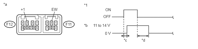
| *1 | Washer Switch | - | - |
| *a | Component without harness connected
(Windshield Wiper Switch Assembly) |
*b | Voltage between terminals F12-3 (+1) and F11-2 (EW) |
| *c | Approximately 0.5 seconds | *d | Approximately 2.2 seconds |
Connect the positive (+) lead to terminal F12-2 (+B) and the negative (-) lead to terminal F12-1 (+S) and F11-2 (EW).
Connect the positive (+) lead to terminal F12-3 (+1) and the negative (-) lead to terminal F11-2 (EW).
Turn the washer switch on and off, and check the voltage between terminals F12-3 (+1) and F11-2 (EW).
- OK:
Voltage changes as shown in the illustration.
If the result is not as specified, replace the wiper switch.
Check the rear wiper switch (w/ Rear Wiper).
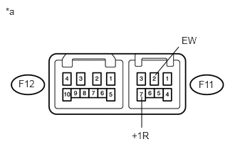
Measure the resistance according to the value(s) in the table below.
| *a | Component without harness connected
(Windshield Wiper Switch Assembly) |
- Standard Resistance:
Rear Wiper Switch Tester Connection Switch Condition Specified Condition F11-7 (+1R) - F11-2 (EW) OFF 10 kΩ or higher F11-7 (+1R) - F11-2 (EW) ON Below 1 Ω
If the result is not as specified, replace the wiper switch.
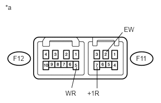
Check the rear washer switch (w/ Rear Wiper).
| *a | Component without harness connected
(Windshield Wiper Switch Assembly) |
Measure the resistance according to the value(s) in the table below.
- Standard Resistance:
Rear Washer Switch Tester Connection Switch Condition Specified Condition F12-5 (WR) - F11-2 (EW) OFF 10 kΩ or higher F11-7 (+1R) - F11-2 (EW) F12-5 (WR) - F11-2 (EW) WASH Below 1 Ω F12-5 (WR) - F11-2 (EW) ON + WASH Below 1 Ω F11-7 (+1R) - F11-2 (EW)
If the result is not as specified, replace the wiper switch.
84650
2.INSPECT WINDSHIELD WIPER SWITCH ASSEMBLY (for RHD)
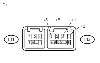
Check the front wiper switch.
| *a | Component without harness connected
(Windshield Wiper Switch Assembly) |
Measure the resistance according to the value(s) in the table below.
- Standard Resistance:
Front Wiper Switch Tester Connection Switch Condition Specified Condition F12-4 (+S) - F12-2 (+1) OFF Below 1 Ω INT F12-3 (+B) - F12-2 (+1) MIST LO F12-3 (+B) - F12-1 (+2) HI
If the result is not as specified, replace the wiper switch.
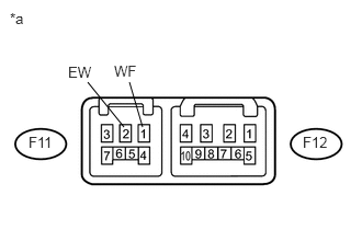
Check the front washer switch.
| *a | Component without harness connected
(Windshield Wiper Switch Assembly) |
Measure the resistance according to the value(s) in the table below.
- Standard Resistance:
Front Washer Switch Tester Connection Switch Condition Specified Condition F11-2 (EW) - F11-1 (WF) ON Below 1 Ω OFF 10 kΩ or higher
If the result is not as specified, replace the wiper switch.
Check the intermittent operation.
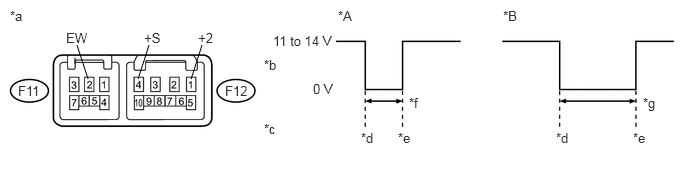
| *A | FAST: Connect battery negative lead to terminal F12-4 (+S) | *B | SLOW: Connect battery negative lead to terminal F12-4 (+S) |
| *a | Component without harness connected
(Windshield Wiper Switch Assembly) |
*b | Voltage between terminals F12-1 (+2) and F11-2 (EW) |
| *c | Wiper Switch | *d | Stop |
| *e | Start | *f | 1.6 +/- 1 seconds |
| *g | 10.7 +/- 5 seconds | - | - |
Connect the positive (+) lead to terminal F12-2 (+1) and the negative (-) lead to terminal F11-2 (EW).
Connect the positive (+) lead to terminal F12-3 (+B) and the negative (-) lead to terminal F11-2 (EW) and F12-4 (+S).
Turn the wiper switch to the INT position.
Connect the positive (+) lead to terminal F12-4 (+S) for 5 seconds.
Connect the negative (-) lead to terminal F12-4 (+S).
Operate the intermittent wiper relay and check the voltage between terminals F12-2 (+1) and F11-2 (EW).
- OK:
Voltage changes as shown in the illustration.
If the result is not as specified, replace the wiper switch.
Check the front washer operation.
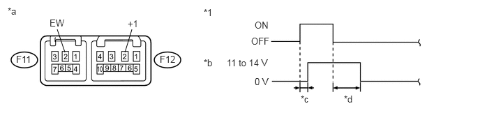
| *1 | Washer Switch | - | - |
| *a | Component without harness connected
(Windshield Wiper Switch Assembly) |
*b | Voltage between terminals F12-2 (+1) and F11-2 (EW) |
| *c | Approximately 0.5 seconds | *d | Approximately 2.2 seconds |
Connect the positive (+) lead to terminal F12-3 (+B) and the negative (-) lead to terminal F12-1 (+S) and F11-2 (EW).
Connect the positive (+) lead to terminal F12-2 (+1) and the negative (-) lead to terminal F11-2 (EW).
Turn the washer switch on and off, and check the voltage between terminals F12-2 (+1) and F11-2 (EW).
- OK:
Voltage changes as shown in the illustration.
If the result is not as specified, replace the wiper switch.
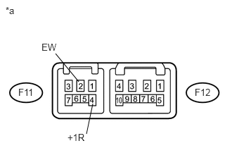
Check the rear wiper switch (w/ Rear Wiper).
| *a | Component without harness connected
(Windshield Wiper Switch Assembly) |
Measure the resistance according to the value(s) in the table below.
- Standard Resistance:
Rear Wiper Switch Tester Connection Switch Condition Specified Condition F11-4 (+1R) - F11-2 (EW) OFF 10 kΩ or higher F11-4 (+1R) - F11-2 (EW) ON Below 1 Ω
If the result is not as specified, replace the wiper switch.
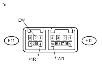
Check the rear washer switch (w/ Rear Wiper).
| *a | Component without harness connected
(Windshield Wiper Switch Assembly) |
- Standard Resistance:
Rear Washer Switch Tester Connection Switch Condition Specified Condition F12-10 (WR) - F11-2 (EW) OFF 10 kΩ or higher F11-4 (+1R) - F11-2 (EW) F12-10 (WR) - F11-2 (EW) WASH Below 1 Ω F12-10 (WR) - F11-2 (EW) ON + WASH Below 1 Ω F11-4 (+1R) - F11-2 (EW)
If the result is not as specified, replace the wiper switch.