RM19S0E
_59
Vehicle Exterior
_051505
LIGHTING (EXT)
_0248427
AUTOMATIC HEADLIGHT BEAM LEVEL CONTROL SYSTEM
J
LIGHTING (EXT) AUTOMATIC HEADLIGHT BEAM LEVEL CONTROL SYSTEM Indicator Circuit
DESCRIPTION
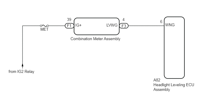
The headlight beam level control system indicator light in the combination meter assembly comes on for approximately 3 seconds when the ignition switch is turned to ON. The indicator light also comes on when the headlight leveling ECU assembly detects a malfunction.
WIRING DIAGRAM
1.427,0.948 1.75,1.104
0.323,0.156
10
false
MET
0.302,2.438 1.302,2.594
1,0.156
10
false
from IG2 Relay
2.49,1.281 4.333,1.521
1.844,0.24
10
false
Combination Meter Assembly
5.417,2.74 5.708,2.896
0.292,0.156
10
false
A82
2.365,0.604 2.552,0.76
0.188,0.156
10
false
39
2.365,0.823 2.552,0.979
0.188,0.156
10
false
F1
2.656,0.802 2.948,0.99
0.292,0.188
10
false
IG+
3.76,0.802 4.271,1.01
0.51,0.208
10
false
LVWG
4.292,0.833 4.479,0.99
0.188,0.156
10
false
F3
4.323,0.604 4.448,0.76
0.125,0.156
10
false
4
5.417,2.906 6.958,3.24
1.542,0.333
10
false
Headlight Leveling ECU Assembly
5.833,0.792 6.208,0.948
0.375,0.156
10
false
WNG
5.656,0.677 5.781,0.833
0.125,0.156
10
false
6
PROCEDURE
1.CHECK HEADLIGHT LEVELING ECU ASSEMBLY (INPUT SIGNAL)
a.
0.096,0.071 0.351,0.263
0.255,0.192
10
*a
1.638,0.486 1.957,0.648
0.318,0.163
10
A82
2.71,0.457 3.120,0.620
0.411,0.163
10
WNG
2.658,0.553 2.374,1.246
false
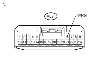
Disconnect the headlight leveling ECU assembly connector.
b.
Measure the voltage according to the value(s) in the table below.
- Standard Voltage:
Tester Connection Switch Condition Specified Condition A82-6 (WNG) - Body ground Ignition switch ON 11 to 14 V A82-6 (WNG) - Body ground Ignition switch off Below 1 V
| *a | Front view of wire harness connector
(to Headlight Leveling ECU Assembly) |
OK
PROCEED TO NEXT SUSPECTED AREA SHOWN IN PROBLEM SYMPTOMS TABLE
(See pageVehicle Exterior>LIGHTING (EXT)>AUTOMATIC HEADLIGHT BEAM LEVEL CONTROL SYSTEM>PROBLEM SYMPTOMS TABLE)
NG
2.CHECK HARNESS AND CONNECTOR (COMBINATION METER ASSEMBLY - HEADLIGHT LEVELING ECU ASSEMBLY)
2.CHECK HARNESS AND CONNECTOR (COMBINATION METER ASSEMBLY - HEADLIGHT LEVELING ECU ASSEMBLY)
a.
Disconnect the F3 combination meter assembly connector.
b.
Measure the resistance according to the value(s) in the table below.
- Standard Resistance:
Tester Connection Condition Specified Condition A82-6 (WNG) - F3-4 (LVWG) Always Below 1 Ω A82-6 (WNG) or F3-4 (LVWG) - Body ground Always 10 kΩ or higher
OK
GO TO METER / GAUGE SYSTEM
(See pageVehicle Interior>METER / GAUGE / DISPLAY>METER / GAUGE SYSTEM>HOW TO PROCEED WITH TROUBLESHOOTING)
NG
REPAIR OR REPLACE HARNESS OR CONNECTOR