2NZ-FE ENGINE MECHANICAL CYLINDER HEAD REASSEMBLY
CAUTION / NOTICE / HINT
- HINT:
-
Perform "Inspection After Repairs" after replacing the cylinder head sub-assembly.
-
Click hereEngine / Hybrid System>2NZ-FE ENGINE CONTROL>SFI SYSTEM>INITIALIZATION
PROCEDURE

 11151A
1.INSTALL CAMSHAFT BEARING CAP SETTING RING PIN
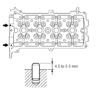
Using a plastic-faced hammer, tap a new ring pin in to the specified protrusion height.
- Protrusion height:
4.5 to 5.5 mm (0.177 to 0.217 in.)
17111Z
2.INSTALL STUD BOLT
Using "TORX" socket wrenches E5 and E7, install the 11 stud bolts.
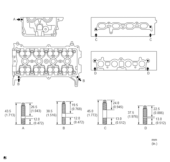
- Torque:
- Bolt A, C : 10 N*m (102 kgf*cm, 7 ft.*lbf)
- Bolt B : 4.0 N*m (41 kgf*cm, 35 in.*lbf)
- Bolt D : 9.0 N*m (92 kgf*cm, 80 in.*lbf)
13711E
3.INSTALL VALVE STEM OIL SEAL
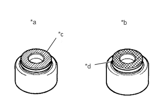
Apply a light coat of engine oil to the valve stem oil seal.
| *a | Intake |
| *b | Exhaust |
| *c | Gray |
| *d | Black |
- NOTICE:
-
Installing the oil seal for intake and exhaust onto the opposite valve guide bush may cause failures.
- HINT:
-
The intake valve oil seal is gray and the exhaust valve oil seal is black.
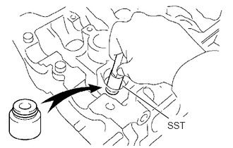
Using SST, push in a new oil seal.
- SST
- 09201-41020
13711
4.INSTALL INTAKE VALVE
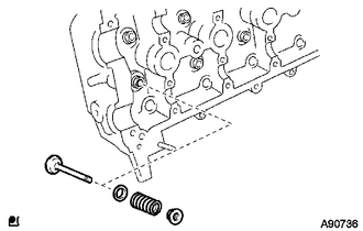
Install the valve, spring seat, valve spring, and spring retainer.
- NOTICE:
-
Install the parts into their original locations in the original order.
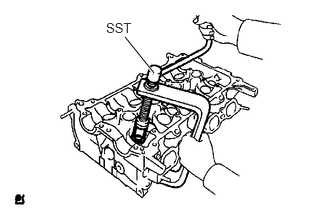
Using SST, compress the spring and install the 2 retainer locks.
- SST
- 09202-70020 (09202-00010)
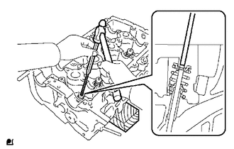
Using a pin-punch (5 mm) and the valve stem (not in use) with its tip wrapped in tape, gently tap the valve stem tip to ensure a proper fit.
- NOTICE:
-
Do not damage the valve stem tip.
13715
5.INSTALL EXHAUST VALVE
Install the valve, spring seat, valve spring, and spring retainer.
Using SST, compress the spring and install the 2 retainer locks.
- SST
- 09202-70020 (09202-00010)
Using a pin-punch (5 mm) and the valve stem (not in use) with the tip wrapped in tape, lightly tap the valve stem tip to ensure a proper fit.
- NOTICE:
-
Do not damage the valve stem tip.
15678A
6.INSTALL OIL CONTROL VALVE FILTER
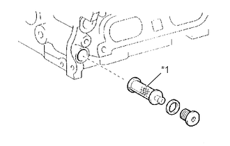
Install the oil control valve filter.
| *1 | Oil Control Valve Filter |
11117B
7.INSTALL NO. 2 WITH HEAD TAPER SCREW PLUG
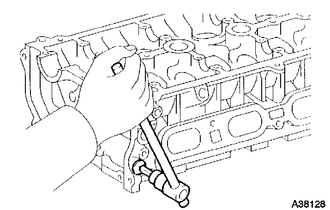
Using an 8 mm socket hexagon wrench, install the No. 2 with head taper screw plug and a new gasket.
- Torque:
- 30 N*m (306 kgf*cm, 22 ft.*lbf)
11117A
8.INSTALL NO. 1 WITH HEAD TAPER SCREW PLUG
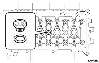
Using a 14 mm socket hexagon wrench, install the No. 1 with head taper screw plug and a new gasket.
- Torque:
- 30 N*m (306 kgf*cm, 22 ft.*lbf)