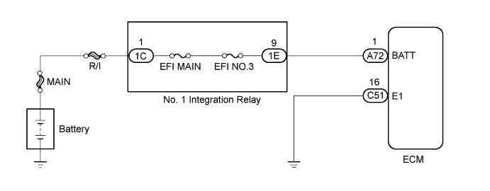
DTC P0560 System Voltage |
| DTC No. | DTC Detection Condition | Trouble Area |
| P0560 | An open in the ECM back up power source circuit (1 trip detection logic) |
|
| Related DTCs | P0560: ECM System Voltage |
| Required Sensors/Components (Main) | ECM |
| Required Sensors/Components (Related) | - |
| Frequency of Operation | Continuous |
| Duration | 3 seconds |
| MIL Operation | Immediate (MIL illuminated after next engine start) |
| Sequence of Operation | None |
| Monitor runs whenever following DTCs not present | None |
| Stand-by RAM | Initialized |
| Battery voltage | Below 3.5 V |
| Techstream Display | Description |
| NORMAL |
|
| ABNORMAL |
|
| INCOMPLETE |
|
| N/A |
|
| 1.INSPECT BATTERY |
Check that the battery is not depleted (Click here).
|
| ||||
| OK | |
 |
| 2.CHECK BATTERY TERMINAL |
Check that the battery terminals are not loose or corroded.
|
| ||||
| OK | |
|
| 3.CHECK HARNESS AND CONNECTOR (ECM - BATTERY) |
Disconnect the cable from the negative (-) battery terminal.
Disconnect the cable from the positive (+) battery terminal.
Disconnect the ECM connector.
Measure the resistance according to the value(s) in the table below.
| Tester Connection | Condition | Specified Condition |
| A72-1 (BATT) - Battery positive (+) terminal | Always | Below 1 Ω |
| A72-1 (BATT) or Battery positive (+) terminal - Body ground | Always | 10 kΩ or higher |
Reconnect the ECM connector.
Reconnect the cable to the positive (+) battery terminal.
Reconnect the cable to the negative (-) battery terminal.
|
| ||||
| OK | |
|
| 4.CHECK WHETHER DTC OUTPUT RECURS (DTC P0560) |
Connect the Techstream to the DLC3.
Turn the ignition switch to ON.
Turn the Techstream on.
Clear the DTCs (Click here).
Turn the ignition switch off and wait for at least 30 seconds.
Turn the ignition switch to ON and turn the Techstream on.
Wait 5 seconds or more.
Enter the following menus: Powertrain / Engine and ECT / Trouble Codes.
Read DTCs.
| Result | Proceed to |
| DTC P0560 is output | A |
| DTC is not output | B |
|
| ||||
| A | ||
 | ||
| ||
