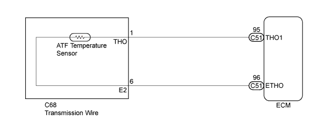
DTC P0712 Transmission Fluid Temperature Sensor "A" Circuit Low Input |
DTC P0713 Transmission Fluid Temperature Sensor "A" Circuit High Input |
| DTC No. | DTC Detection Condition | Trouble Area |
| P0712 | ATF temperature sensor resistance is less than 79 Ω for 0.5 seconds or more (1 trip detection logic). |
|
| P0713 | ATF temperature sensor resistance is more than 156 kΩ for 0.5 seconds or more and either of the following conditions is met (1 trip detection logic). |
|
| (A) 10 minutes or more have elapsed after the engine start when engine coolant temperature or intake air temperature is -29.375°C (-20.875°F) or less. | ||
| (B) 10 seconds or more have elapsed after the engine start when engine coolant temperature and intake air temperature are more than -29.375°C (-20.875°F). |
| Related DTCs | P0712: ATF temperature sensor/Range check (Low resistance) P0713: ATF temperature sensor/Range check (High resistance) |
| Required sensors/Components | ATF temperature sensor |
| Frequency of operation | Continuous |
| Duration | 0.5 seconds |
| MIL operation | Immediate |
| Sequence of operation | None |
| The monitor runs whenever the following DTCs are not present. | None |
| Engine coolant temperature or intake air temperature at engine start | -29.375°C (-20.875°F) or less |
| Time after engine start | 10 minutes or more |
| ECT sensor circuit fail (P0115, P0117, P0118) | Not detected |
| IAT sensor circuit fail (P0112, P0113) | Not detected |
| Engine coolant temperature and intake air temperature at engine start | More than -29.375°C (-20.875°F) |
| Time after engine start | 10 seconds or more |
| ECT sensor circuit fail (P0115, P0117, P0118) | Not detected |
| IAT sensor circuit fail (P0112, P0113) | Not detected |
| ATF temperature sensor voltage (ATF temperature sensor output temperature) | Less than 0.14 V (Higher than 164°C (327.2°F)) |
| ATF temperature sensor voltage (ATF temperature sensor output temperature) | More than 4.91 V (Less than -48°C (-54.4°F)) |
| ATF temperature sensor voltage (ATF temperature sensor output temperature) | 0.14 V to 4.91 V (-48 to 164°C (-54.4 to 327.2°F) |
| DATA LIST |
Warm up the engine.
Turn the ignition switch off.
Connect the Techstream to the DLC3.
Turn the ignition switch to ON.
Turn the Techstream on.
Enter the following menus: Powertrain / Engine and ECT / Data List / All Data.
In accordance with the display on the Techstream, read the Data List.
| Tester Display | Measurement Item/Range | Normal Condition | Diagnostic Note |
| A/T Oil Temperature 1 | ATF Temperature Sensor Value/ min.: -40°C (-40°F) max.: 215°C (419°F) |
| If the value is "-40°C (-40°F)" or "150°C (302°F) or more", ATF temperature sensor circuit is opened or shorted. |
| Temperature Displayed | Malfunction |
| -40°C (-40°F) | Open circuit |
| 150°C (302°F) or more | Short circuit |
| 1.INSPECT TRANSMISSION WIRE (ATF TEMPERATURE SENSOR) |
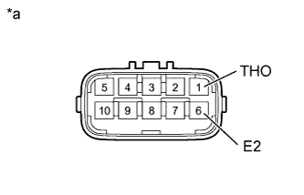 |
Disconnect the C68 transmission wire connector.
Measure the resistance according to the value(s) in the table below.
| Tester Connection | Condition | Specified Condition |
| 1 (THO) - 6 (E2) | Always | 79 Ω to 156 kΩ |
| 1 (THO) - Body ground | Always | 10 kΩ or higher |
| 6 (E2) - Body ground | Always | 10 kΩ or higher |
| *a | Component without harness connected (Transmission Wire) |
| ATF Temperature | Specified Condition |
| 10°C (50°F) | 5 to 8 kΩ |
| 25°C (77°F) | 2.5 to 4.5 kΩ |
| 110°C (230°F) | 0.22 to 0.28 kΩ |
|
| ||||
| OK | |
 |
| 2.CHECK HARNESS AND CONNECTOR (TRANSMISSION WIRE - ECM) |
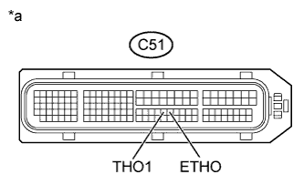 |
Connect the C68 transmission wire connector.
Disconnect the ECM connector.
Measure the resistance according to the value(s) in the table below.
| Tester Connection | Condition | Specified Condition |
| C51-95 (THO1) - C51-96 (ETHO) | Always | 79 Ω to 156 kΩ |
| C51-95 (THO1) - Body ground | Always | 10 kΩ or higher |
| C51-96 (ETHO) - Body ground | Always | 10 kΩ or higher |
| *a | Front view of wire harness connector (to ECM) |
|
| ||||
| OK | ||
 | ||
| ||
