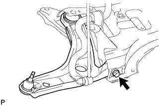
FRONT LOWER SUSPENSION ARM (for Sedan RH Side) > INSTALLATION |
| 1. TEMPORARILY TIGHTEN FRONT LOWER SUSPENSION ARM RH |
|
Install the lower arm onto the crossmember and provisionally tighten the bolt.
| 2. INSTALL FRONT SUSPENSION CROSSMEMBER SUB-ASSEMBLY |
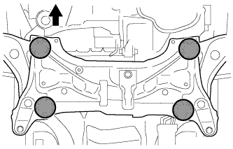 |
Place wooden blocks or plate lift attachments on an engine lifter, and then set the front suspension crossmember sub-assembly so that the attachments are in the positions shown in the illustration.
 | Front of the Vehicle |
 | Attachment Placement Positions |
Temporarily install the front suspension crossmember sub-assembly to the body with the 6 bolts.
By inserting SST into the datum holes in the front suspension crossmember RH and LH alternately, tighten bolts A, B and C on both sides to the specified torque, in several steps.
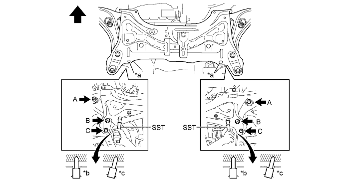
| *a | Datum Hole | *b | OK |
| *c | NG | - | - |
| Front of the Vehicle | - | - |
Install the engine moving control rod with the bolt.
| 3. INSTALL FRONT LOWER SUSPENSION ARM LH |
Install the front lower suspension arm sub-assembly LH to the steering knuckle with a new castle nut.
Install a new clip.
| 4. INSTALL FRONT LOWER SUSPENSION ARM RH |
| 5. INSTALL TIE ROD END SUB-ASSEMBLY LH |
Install the tie rod end sub-assembly LH to the steering knuckle with a new castle nut.
Install a new cotter pin.
| 6. INSTALL TIE ROD END SUB-ASSEMBLY RH |
| 7. INSTALL FRONT STABILIZER LINK ASSEMBLY LH |
Install the front stabilizer link assembly LH with the nut.
| 8. INSTALL FRONT STABILIZER LINK ASSEMBLY RH |
| 9. INSTALL STEERING COLUMN HOLE COVER SUB-ASSEMBLY |
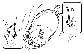 |
Install clip B to the body portion and install the No. 1 steering column hole cover sub-assembly to the body portion with clip A.
| 10. INSTALL STEERING SLIDING YOKE SUB-ASSEMBLY |
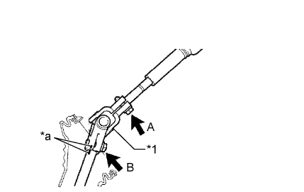 |
Align the matchmarks and install the steering sliding yoke sub-assembly to the power steering gear.
| *1 | Steering Sliding Yoke Sub-assembly |
| *a | Matchmark |
Install bolt B.
Tighten bolt A.
| 11. INSTALL COLUMN HOLE COVER SILENCER SHEET |
Install the column hole cover silencer sheet with the 2 clips.
Install the floor carpet.
| 12. INSTALL FRONT WHEEL |
| 13. POSITION WHEELS FACING STRAIGHT AHEAD |
| 14. STABILIZE SUSPENSION |
Lower the vehicle from the jack.
Bounce the vehicle up and down several times to stabilize the suspension.
| 15. FULLY TIGHTEN FRONT LOWER SUSPENSION ARM RH |
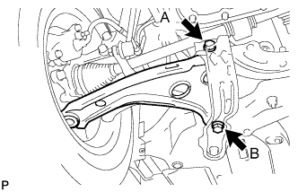 |
Fully tighten the 2 bolts.
| 16. INSTALL OUTER COWL TOP PANEL |
Install the cowl top panel outer with the 8 bolts.
Install the cowl top to cowl inner brace with the 2 bolts.
Connect the wire harness clamp.
| 17. INSTALL FRONT AIR SHUTTER SEAL |
Engage the 3 claws to install the front air shutter seal RH.
| 18. INSTALL FRONT WIPER MOTOR AND LINK |
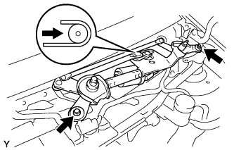 |
Connect the connector.
Slide the wiper link as shown in the illustration and engage the rubber pin with the body.
Install the front wiper motor and link with the 2 bolts.
| 19. INSTALL COWL TOP VENTILATOR LOUVER SUB-ASSEMBLY |
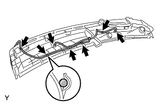 |
Connect the washer hoses.
Engage the 5 hooks.
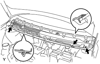 |
Engage the 8 hooks and the 4 claws.
Install the cowl top ventilator louver sub-assembly with the 3 clips.
| 20. INSTALL COWL SIDE VENTILATOR SUB-ASSEMBLY LH |
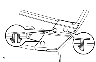 |
Engage the 3 claws and install the cowl side ventilator sub-assembly LH.
| 21. INSTALL COWL SIDE VENTILATOR SUB-ASSEMBLY RH |
| 22. INSTALL FRONT WIPER ARM AND BLADE ASSEMBLY LH |
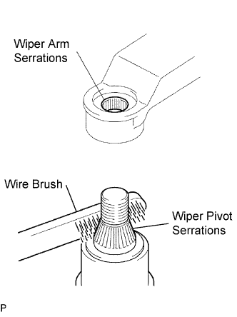 |
Scrape any metal powder off the serrated part of the wiper arm with a round file or the equivalent (when reinstalling).
Clean the wiper pivot serrations with a wire brush.
Operate the wiper, then stop the windshield wiper motor in the automatic stop position.
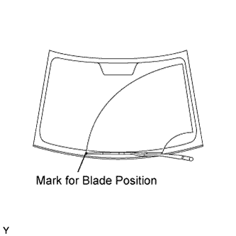 |
Align the blade tip with the mark on the windshield glass, as shown in the illustration.
Tighten the nut of the front wiper arm.
| 23. INSTALL FRONT WIPER ARM AND BLADE ASSEMBLY RH |
|
Scrape any metal powder off the serrated part of the wiper arm with a round file or the equivalent (when reinstalling).
Clean the wiper pivot serrations with a wire brush.
Operate the wiper, then stop the windshield wiper motor in the automatic stop position.
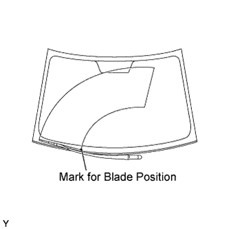 |
Align the blade tip with the mark on the windshield glass, as shown in the illustration.
Tighten the nut of the front wiper arm.
| 24. INSTALL FRONT WIPER ARM HEAD CAP |
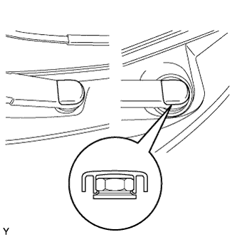 |
Engage the claw and install the 2 front wiper arm head caps.
| 25. TEMPORARILY TIGHTEN HOOD SUB-ASSEMBLY |
Provisionally install the hood with the 4 bolts.
| 26. INSPECT HOOD SUB-ASSEMBLY |
Check that the clearance measurements are within the standard ranges.
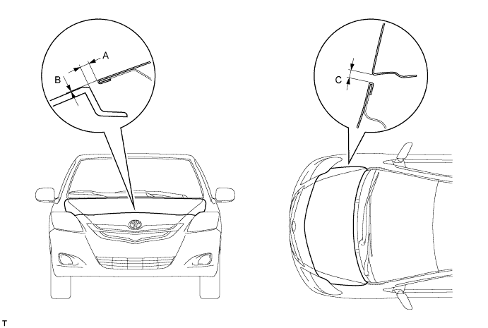
| Area | Measurement | Area | Measurement |
| A | 2.35 to 6.35 mm (0.092 to 0.250 in.) | C | 2.0 to 5.0 mm (0.079 to 0.197 in.) |
| B | -2 to 2 mm (-0.079 to 0.079 in.) | - | - |
| 27. ADJUST HOOD SUB-ASSEMBLY |
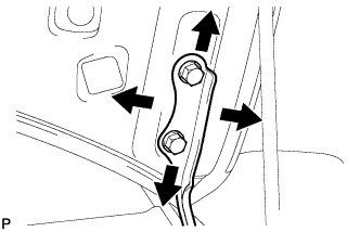 |
Loosen the hood side hinge bolts.
Move the hood to adjust the clearance to within the standard range.
Tighten the hood side hinge bolts after the adjustment.
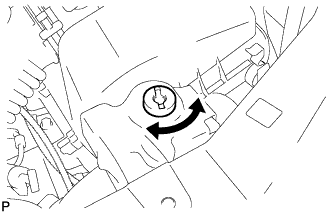 |
Adjust the height of the hood front end by turning the cushion rubber.
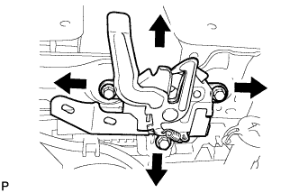 |
Adjust the hood lock.
Loosen the 3 bolts.
Adjust the hood lock position so that the striker can enter it smoothly.
Tighten the 3 bolts after the adjustment.
| 28. CONNECT CABLE TO NEGATIVE BATTERY TERMINAL |
| 29. INSPECT AND ADJUST FRONT WHEEL ALIGNMENT |