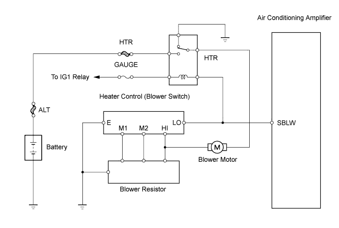
AIR CONDITIONING SYSTEM (for Sedan) > Blower Motor Circuit |
| 1.INSPECT FUSE (GAUGE, HTR) |
Remove the GAUGE fuse from the main body ECU.
Remove the HTR fuse from the engine room relay block.
Measure the resistance.
| Tester Item | Specified Condition |
| GAUGE fuse | Below 1 Ω |
| HTR fuse | Below 1 Ω |
Reinstall the GAUGE fuse.
Reinstall the HTR fuse.
|
| ||||
| OK | |
 |
| 2.INSPECT HTR RELAY |
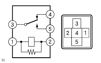 |
Remove the HTR relay from the main body ECU.
Measure the resistance.
| Tester Connection | Specified Condition |
| 3 - 4 | Below 1 Ω |
| 3 - 5 | 10 kΩ or higher |
| 3 - 4 | 10 kΩ or higher (when battery voltage is applied to terminals 1 and 2) |
| 3 - 5 | Below 1 Ω (when battery voltage is applied to terminals 1 and 2) |
Reinstall the HTR relay.
|
| ||||
| OK | |
|
| 3.INSPECT BLOWER MOTOR |
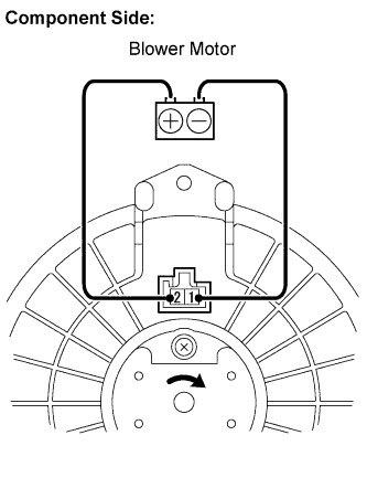 |
Disconnect the E4 blower motor connector.
Connect the positive (+) lead from the battery to terminal 2 and the negative (-) lead to terminal 1, then check that the blower motor operates smoothly.
Measure the current.
| Tester Connection | Specified Condition |
| E4-2 (+B) - E4-1 (GND) | 1 to 3 A |
Reconnect the blower motor connector.
|
| ||||
| OK | |
|
| 4.CHECK HARNESS AND CONNECTOR (HTR FUSE - MAIN BODY ECU) |
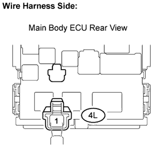 |
Disconnect the 4L main body ECU connector.
Measure the voltage.
| Tester Connection | Condition | Specified Condition |
| 4L-1 - Body ground | Always | 11 to 14 V |
Reconnect the main body ECU connector.
|
| ||||
| OK | |
|
| 5.CHECK MAIN BODY ECU |
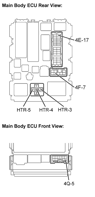 |
Remove the HTR relay from the main body ECU.
Measure the resistance.
| Tester Connection | Specified Condition |
| 4F-7 - HTR-3 | Below 1 Ω |
| 4E-17 - HTR-4 | Below 1 Ω |
Measure the voltage.
| Tester Connection | Condition | Specified Condition |
| HTR-5 - Body ground | Always | 11 to 14 V |
Reinstall the HTR relay.
Measure the voltage.
| Tester Connection | Condition | Specified Condition |
| 4Q-5 - Body ground | Ignition switch ON | 11 to 14 V |
|
| ||||
| OK | |
|
| 6.CHECK HARNESS AND CONNECTOR (MAIN BODY ECU - HEATER CONTROL (BLOWER SWITCH)) |
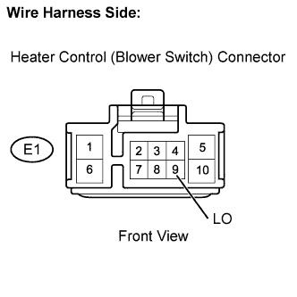 |
Disconnect the E1 heater control (blower switch) connector.
Measure the voltage.
| Tester Connection | Condition | Specified Condition |
| E1-9 (LO) - Body ground | Ignition switch ON | 11 to 14 V |
Reconnect the heater control (blower switch) connector.
|
| ||||
| OK | |
|
| 7.CHECK HARNESS AND CONNECTOR (MAIN BODY ECU - BLOWER MOTOR) |
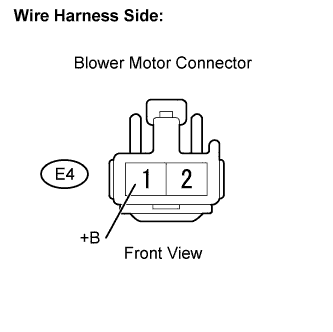 |
Disconnect the E4 blower motor connector.
Measure the voltage.
| Tester Connection | Condition | Specified Condition |
| E4-1 (+B) - Body ground | Ignition switch ON | 11 to 14 V |
Reconnect the blower motor connector.
|
| ||||
| OK | |
|
| 8.CHECK HARNESS AND CONNECTOR (BLOWER RESISTOR - BLOWER MOTOR) |
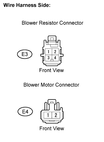 |
Disconnect the E3 blower resistor connector.
Disconnect the E4 blower motor connector.
Measure the resistance.
| Tester Connection | Specified Condition |
| E3-4 - E4-1 | Below 1 Ω |
Reconnect the blower resistor connector.
Reconnect the blower motor connector.
|
| ||||
| OK | |
|
| 9.INSPECT BLOWER RESISTOR |
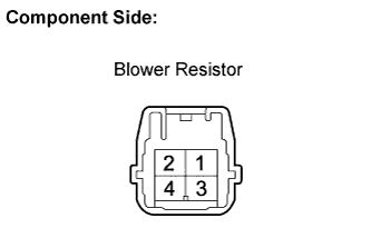 |
Remove the blower resistor.
Measure the resistance.
| Tester Connection | Specified Condition |
| 4 - 1 | 3.12 to 3.60Ω |
| 4 - 3 | 1.45 to 1.67Ω |
| 4 - 2 | 0.52 to 0.60Ω |
Reinstall the blower resistor.
|
| ||||
| OK | |
|
| 10.INSPECT HEATER CONTROL (BLOWER SWITCH) |
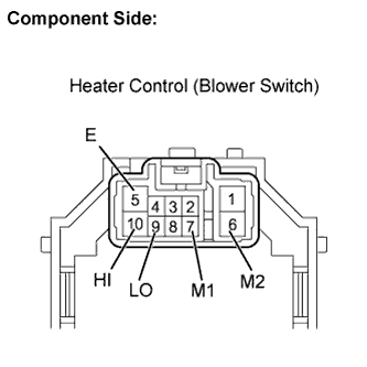 |
Remove the heater control (blower switch).
Measure the resistance.
| Switch Position | Tester Connection | Specified Condition |
| 0 | ALL - 5 (E) | 10 kΩ or higher |
| 1 | 9 (LO) - 5 (E) | Below 1 Ω |
| 1 - 2 | 9 (LO) - 5 (E) - 7 (M1) | Below 1 Ω |
| 2 | 9 (LO) - 5 (E) - 7 (M1) | Below 1 Ω |
| 2 - 3 | 9 (LO) - 5 (E) - 7 (M1) - 6 (M2) | Below 1 Ω |
| 3 | 9 (LO) - 5 (E) - 6 (M2) | Below 1 Ω |
| 3 - 4 | 9 (LO) - 5 (E) - 6 (M2) - 10 (HI) | Below 1 Ω |
| 4 | 9 (LO) - 5 (E) - 10 (HI) | Below 1 Ω |
Reinstall the heater control (blower switch).
|
| ||||
| OK | |
|
| 11.CHECK HARNESS AND CONNECTOR (HEATER CONTROL (BLOWER SWITCH) - BLOWER RESISTOR) |
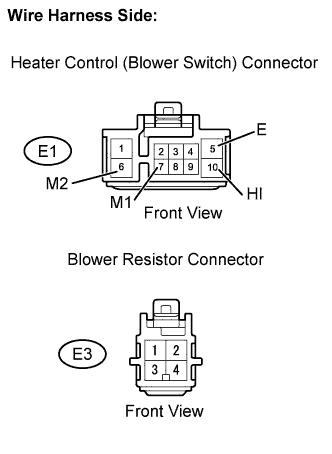 |
Disconnect the E1 heater control (blower switch) connector.
Disconnect the E3 blower resistor connector.
Measure the resistance.
| Tester Connection | Specified Condition |
| E1-5 (E) - E3-1 | Below 1 Ω |
| E1-6 (M2) - E3-2 | Below 1 Ω |
| E1-7 (M1) - E3-3 | Below 1 Ω |
| E1-10 (HI) - E3-4 | Below 1 Ω |
Reconnect the heater control (blower switch) connector.
Reconnect the blower resistor connector.
|
| ||||
| OK | ||
 | ||
| ||
