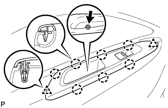
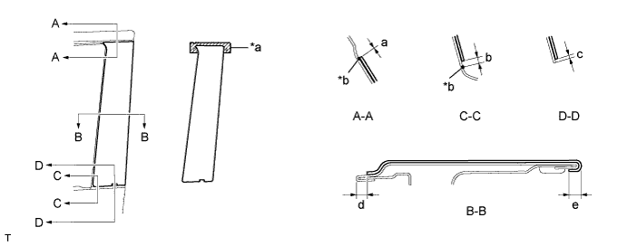
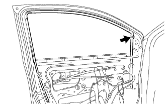
Application precautions:
Application temperature:
- If the temperature is below 15°C (59°F), using an infrared light, heat the base (body attachment surface) and black out tape to between 20 and 30°C (68 and 86°F). If the temperature is over 35°C (95°F), perform the operation after lowering the temperature to below 35°C (95°F).
- HINT:
- The most suitable temperature for applying the black out tape is 25°C (77°F).
- The black out tape cannot be applied correctly at low temperature due to its stiffness and weak adhesion. The tape loses its consistency at high temperature.
- If the temperature is below 15°C (59°F), using an infrared light, heat the base (body attachment surface) and black out tape to between 20 and 30°C (68 and 86°F). If the temperature is over 35°C (95°F), perform the operation after lowering the temperature to below 35°C (95°F).
Pre-application procedure:
- Any uneven twisting or dust on the base (body attachment surface) causes a defective appearance due to air being trapped under the black out tape during application. Make sure there is no uneven twisting or dust on or around the base or black out tape.
- HINT:
- When the air is dry in winter, put cardboard between the pieces of black out tape and keep them in a dry flat place.
- Any uneven twisting or dust on the base (body attachment surface) causes a defective appearance due to air being trapped under the black out tape during application. Make sure there is no uneven twisting or dust on or around the base or black out tape.
Handling:
- Keep the black out tape in a dry flat level place because it is easily deformed.
- NOTICE:
- Do not fold, bend or expose the tape to high temperatures.
- Keep the black out tape in a dry flat level place because it is easily deformed.
Application method (Method of squeegee operation and application for general portions):
- NOTICE:
- The positioning accuracy must be within 1 mm (0.039 in.) when starting the application, otherwise, poor appearance and adhesion will result.
- Do not reuse black out tape that has been removed. It causes deformation and weak adhesion.
- In order to suppress bubble formation, slightly raise the portion not being pressed by the squeegee away from the base. Tilt the squeegee between 40 and 50° (in the pushing direction) and between 30 and 45° (in the pulling direction), and apply 20 to 30 N (2 to 3 kg, 4 to 6 lb) of pressure at a velocity of 3 to 7 cm/sec. while pushing out the air.
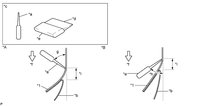
Text in Illustration *A Pushing Direction *B Pulling Direction *1 Black Out Tape - - *a Squeegee *b Backing Paper *c Sectional View *d Non-Padded Side *e Padded Side *f 3 to 7 cm/sec. *g 40 to 50° *h 30 to 45° *i 10 to 20 mm - - - NOTICE:
- While using the squeegee, do not change the speed, stop the operation or change the force of the application. Doing so could cause a streak across the surface of the black out tape called a shock line. While using the squeegee, keep the speed and force of application constant and the angle correct.
- HINT:
- The squeegee can be tilted in either the pushing direction or in the pulling direction against the attachment portion.
- Perform the procedure while peeling the backing paper off the black out tape, 10 to 20 mm (0.394 to 0.787 in.) from the end of the squeegee.
Application method (Method of squeegee operation and application method for hemming portions):
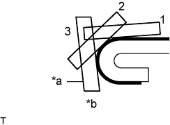
Text in Illustration *a Squeegee *b Hemming Portion - If the tape cannot be pressed in one step using the squeegee, perform the application in several steps. Using your finger or a thicker part of the squeegee, gradually apply the tape to the small R portion of the hemming portion in 2 or 3 steps.
- HINT:
- Peel off the backing paper at the hemming portion and apply the black out tape with your finger or a thicker part of the squeegee.
- If the tape cannot be pressed in one step using the squeegee, perform the application in several steps. Using your finger or a thicker part of the squeegee, gradually apply the tape to the small R portion of the hemming portion in 2 or 3 steps.
Application method (Method of squeegee operation and application method for corner sections):
- Carefully apply the tape using a finger after peeling the backing paper off the corner section.
- In order to prevent appearance deterioration caused by the tape pin angle, turn in the tape at the corner after heating the black out tape with a dryer.
- Carefully apply the tape using a finger after peeling the backing paper off the corner section.
Inspection:
- Repeat the application using new black out tape.
- NOTICE:
- Do not use a needle to rectify bubbles in any glazed tape being applied to the outer panel, in order to make scratches virtually imperceptible.
- HINT:
- Use an instant adhesive if the hemming or corner portions of the black out tape are partially peeled off.
- Repeat the application using new black out tape.
 |