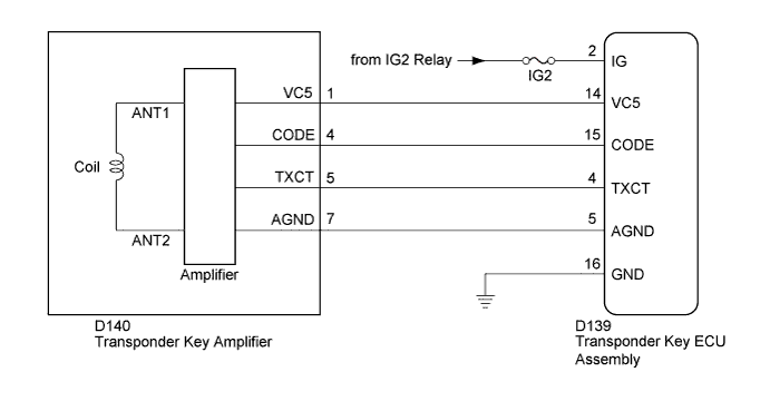
ENGINE IMMOBILISER SYSTEM (for Hatchback) > Engine does not Start because No Initial Combustion |
| 1.CLEAR DTC |
Clear the DTCs (Click here).
| NEXT | |
 |
| 2.CHECK FOR DTC |
Check for DTCs (Click here).
| Result | Proceed to |
| No DTC output | A |
| DTC output | B |
|
| ||||
| A | |
|
| 3.READ VALUE USING TECHSTREAM (IMMOBILISER FUEL CUT) |
Turn the ignition switch off.
Connect the Techstream to the DLC3.
Turn the ignition switch to ON.
Turn the Techstream on.
Enter the following menus: Powertrain / Engine and ECT / Data List.
| Tester Display | Measurement Item/Range | Normal Condition | Diagnostic Note |
| Immobiliser Fuel Cut | Status of immobiliser fuel cut/ ON or OFF | - | - |
| Result | Proceed to |
| NG | A |
| OK | B |
|
| ||||
| A | |
|
| 4.CHECK THEFT WARNING INDICATOR LIGHT OPERATION |
When the key inserted in ignition key cylinder, check that the theft warning indicator light assembly off.
|
| ||||
| OK | ||
 | ||
| ||
| 5.CHECK THEFT WARNING INDICATOR LIGHT OPERATION |
Perform inspection using a different key that has been registered to the vehicle.
When the key inserted in ignition key cylinder, check that the theft warning indicator light assembly off.
|
| ||||
| OK | |
|
| 6.CHECK WHETHER ENGINE STARTS WITH OTHER KEYS |
Perform inspection using a different key that has been registered to the vehicle.
It leaves for 5 seconds by the ignition switch ON status, and the engine starting operation is done.
| Result | Proceed to |
| Engine can not be started | A |
| Engine can be started | B |
|
| ||||
| A | ||
| ||
| ||
| 7.CHECK TRANSPONDER KEY AMPLIFIER (VC5 SIGNAL) |
Disconnect the D140 transponder key amplifier connector.
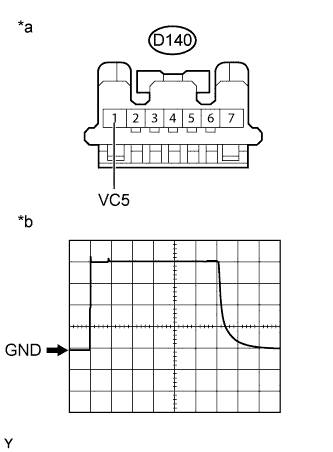 |
Using an oscilloscope, check the waveform.
Waveform
| Item | Content |
| Tester Connection | D140-1 (VC5) - Body ground |
| Tool Setting | 1 V/DIV., 20 ms./DIV. |
| Condition | Key inserted in ignition key cylinder |
| *a | Front view of wire harness connector (to Transponder Key Amplifier) |
| *b | Waveform |
|
| ||||
| OK | ||
| ||
| ||
| 8.CHECK HARNESS AND CONNECTOR (TRANSPONDER KEY AMPLIFIER - TRANSPONDER KEY ECU ASSEMBLY, IG TERMINAL VOLTAGE) |
Disconnect the D140 transponder key amplifier connector.
Disconnect the D139 transponder key ECU assembly connector.
Measure the resistance according to the value(s) in the table below.
| Tester Connection | Condition | Specified Condition |
| D140-1 (VC5) - D139-14 (VC5) | Always | Below 1 Ω |
| D140-7 (AGND) - D139-5 (AGND) | Always | Below 1 Ω |
| D140-1 (VC5) - Body ground | Always | 10 kΩ or higher |
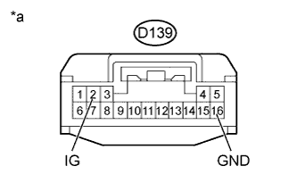 |
Reconnect the transponder key amplifier connector.
Measure the voltage according to the value(s) in the table below.
| Tester Connection | Switch Condition | Specified Condition |
| D139-2 (IG) - D139-16 (GND) | Ignition switch ON | 11 to 14 V |
| *a | Front view of wire harness connector (to Transponder Key ECU assembly) |
| Result | Proceed to |
| OK | A |
| NG (Wire harness or connector) | B |
| NG (IG terminal voltage) | C |
|
| ||||
| OK | |
|
| 9.CHECK TRANSPONDER KEY AMPLIFIER (TXCT SIGNAL) |
Disconnect the D140 transponder key amplifier connector.
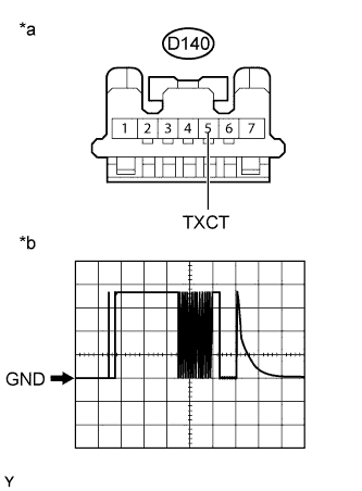 |
Using an oscilloscope, check the waveform.
Waveform
| Item | Content |
| Tester Connection | D140-5 (TXCT) - Body ground |
| Tool Setting | 1 V/DIV., 20 ms./DIV. |
| Condition | Key inserted in ignition key cylinder |
| *a | Front view of wire harness connector (to Transponder Key Amplifier) |
| *b | Waveform |
|
| ||||
| OK | ||
| ||
| ||
| 10.CHECK HARNESS AND CONNECTOR (TRANSPONDER KEY AMPLIFIER - TRANSPONDER KEY ECU ASSEMBLY) |
Disconnect the D140 transponder key amplifier connector.
Disconnect the D139 transponder key ECU assembly connector.
Measure the resistance according to the value(s) in the table below.
| Tester Connection | Condition | Specified Condition |
| D140-5 (TXCT) - D139-4 (TXCT) | Always | Below 1 Ω |
| D140-5 (TXCT) - Body ground | Always | 10 kΩ or higher |
|
| ||||
| OK | |
|
| 11.CHECK TRANSPONDER KEY AMPLIFIER (CODE SIGNAL) |
Disconnect the D140 transponder key amplifier connector.
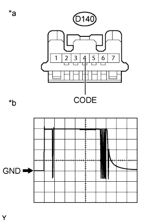 |
Using an oscilloscope, check the waveform.
Waveform
| Item | Content |
| Tester Connection | D140-4 (CODE) - Body ground |
| Tool Setting | 1 V/DIV., 20 ms./DIV. |
| Condition | Key inserted in ignition key cylinder |
| *a | Front view of wire harness connector (to Transponder Key Amplifier) |
| *b | Waveform |
|
| ||||
| OK | ||
| ||
| ||
| 12.CHECK HARNESS AND CONNECTOR (TRANSPONDER KEY AMPLIFIER - TRANSPONDER KEY ECU ASSEMBLY) |
Disconnect the D140 transponder key amplifier connector.
Disconnect the D139 transponder key ECU assembly connector.
Measure the resistance according to the value(s) in the table below.
| Tester Connection | Condition | Specified Condition |
| D140-4 (CODE) - D139-15 (CODE) | Always | Below 1 Ω |
| D140-4 (CODE) - Body ground | Always | 10 kΩ or higher |
Reconnect the transponder key ECU assembly connector.
Reconnect the transponder key amplifier connector.
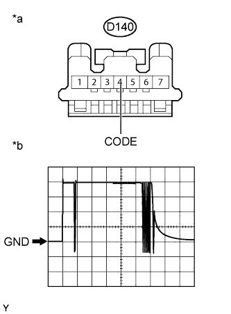 |
Using an oscilloscope, check the waveform.
Waveform
| Item | Content |
| Tester Connection | D140-4 (CODE) - Body ground |
| Tool Setting | 1 V/DIV., 20 ms./DIV. |
| Condition | Key inserted in ignition key cylinder |
| *a | Front view of wire harness connector (to Transponder Key Amplifier) |
| *b | Waveform |
| Result | Proceed to |
| Terminal CODE stuck high (5 V) | A |
| Terminal CODE stuck low (1 V or less) | B |
| Problem in wire harness or connector | C |
|
| ||||
|
| ||||
| A | |
|
| 13.REPLACE TRANSPONDER KEY AMPLIFIER |
Replace the transponder key amplifier (Click here).
| NEXT | |
|
| 14.CHECK WHETHER ENGINE STARTS |
Check that the engine starts with an already registered vehicle key.
|
| ||||
| OK | ||
| ||
| ||
| 15.REPLACE TRANSPONDER KEY ECU ASSEMBLY |
Replace the transponder key ECU assembly with a new one (Click here).
| NEXT | |
|
| 16.REGISTER KEY |
Register the key (Click here).
| NEXT | |
|
| 17.REGISTER ECU COMMUNICATION ID |
Register the ECU communication ID (Click here).
| NEXT | |
|
| 18.CHECK WHETHER ENGINE STARTS |
Check that the engine starts with an already registered vehicle key.
|
| ||||
| OK | ||
| ||
| ||
| 19.REPLACE KEY |
Replace the transponder key master transmitter with a new one (Click here).
| NEXT | |
|
| 20.REREGISTER KEY |
Reregister the key (Click here).
| NEXT | |
|
| 21.CHECK WHETHER ENGINE STARTS |
Check that the engine starts with an already registered vehicle key.
|
| ||||
| OK | ||
| ||
| ||

