Home › Vehicle Interior › HEATING / AIR CONDITIONING › AIR CONDITIONING SYSTEM(for Automatic Air Conditioning System) › 2013.08–2017.10
RM30M0E _58 Vehicle Interior _017118 HEATING / AIR CONDITIONING _0086573 AIR CONDITIONING SYSTEM(for Automatic Air Conditioning System) C

HEATING / AIR CONDITIONING  AIR CONDITIONING SYSTEM(for Automatic Air Conditioning System)  B14B2  Lost Communication with Front Panel LIN  


DESCRIPTION

The air conditioning control assembly communicates with the air conditioning amplifier assembly through the LIN communication system.

If the LIN communication system malfunctions, the air conditioning amplifier assembly does not operate even if the air conditioning control assembly is operated.

DTC No. Detection Item DTC Detection Condition Trouble Area Memory
B14B2 Lost Communication with Front Panel LIN Lost communication with air conditioning control assembly
·

Harness or connector between air conditioning control assembly and power source

·

Harness or connector between air conditioning control assembly and body ground

·

LIN communication system

·

Air conditioning control assembly

·

Air conditioning amplifier assembly

·

Air conditioning harness circuit


Memorized
(10 seconds or more)*1

*1: The air conditioning amplifier assembly stores this DTC if the malfunction has occurred for the period of time indicated in the brackets.


WIRING DIAGRAM
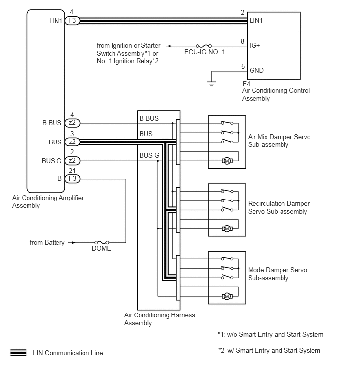
E279033E02
5.26,2.813 6.625,3.198 1.365,0.385 10 false Air Mix Damper Servo Sub-assembly 1.479,0.167 1.635,0.354 0.156,0.188 10 false 4 1.042,0.354 1.396,0.542 0.354,0.188 10 false LIN1 1.448,0.344 1.802,0.531 0.354,0.188 10 false F3 1.458,3.698 1.813,3.885 0.354,0.188 10 false F3 1.458,3.313 1.813,3.5 0.354,0.188 10 false z2 1.458,2.917 1.813,3.104 0.354,0.188 10 false z2 1.458,2.51 1.813,2.698 0.354,0.188 10 false z2 5.104,0.177 5.26,0.365 0.156,0.188 10 false 2 5.104,0.792 5.26,0.979 0.156,0.188 10 false 8 5.115,1.323 5.271,1.51 0.156,0.188 10 false 5 5.292,0.344 5.646,0.531 0.354,0.188 10 false LIN1 5.292,0.875 5.646,1.063 0.354,0.188 10 false IG+ 5.292,1.406 5.646,1.594 0.354,0.188 10 false GND 5.146,1.688 5.5,1.875 0.354,0.188 10 false F4 5.135,1.833 6.604,2.219 1.469,0.385 10 false Air Conditioning Control Assembly 2.052,0.875 3.51,1.417 1.458,0.542 10 false from Ignition or Starter Switch Assembly*1 or No. 1 Ignition Relay*2 3.906,1.01 4.802,1.208 0.896,0.198 10 false ECU-IG NO. 1 0.896,2.521 1.406,2.719 0.51,0.198 10 false B BUS 1.031,2.927 1.542,3.125 0.51,0.198 10 false BUS 0.885,3.323 1.396,3.521 0.51,0.198 10 false BUS G 1.219,3.698 1.438,3.896 0.219,0.198 10 false B 1.49,2.344 1.646,2.531 0.156,0.188 10 false 4 1.49,2.75 1.646,2.938 0.156,0.188 10 false 3 1.49,3.135 1.646,3.323 0.156,0.188 10 false 2 1.458,3.531 1.75,3.719 0.292,0.188 10 false 21 0.26,4.104 1.823,4.5 1.563,0.396 10 false Air Conditioning Amplifier Assembly 0.635,5.052 1.458,5.292 0.823,0.24 10 false from Battery 1.948,5.177 2.417,5.375 0.469,0.198 10 false DOME 2.635,6.594 4.188,6.969 1.552,0.375 10 false Air Conditioning Harness Assembly 0.625,7.396 2.448,7.583 1.823,0.188 10 false : LIN Communication Line 4.615,7 6.927,7.208 2.313,0.208 10 false *1: w/o Smart Entry and Start System 4.625,7.344 6.938,7.552 2.313,0.208 10 false *2: w/ Smart Entry and Start System 2.958,2.427 3.469,2.625 0.51,0.198 10 false B BUS 2.958,2.75 3.469,2.948 0.51,0.198 10 false BUS 2.958,3.208 3.469,3.406 0.51,0.198 10 false BUS G 5.26,4.229 6.615,4.615 1.354,0.385 10 false Recirculation Damper Servo Sub-assembly 5.26,5.635 6.542,6.021 1.281,0.385 10 false Mode Damper Servo Sub-assembly

CAUTION / NOTICE / HINT

NOTICE:

Inspect the fuses for circuits related to this system before performing the following procedure.


HINT:

DTCs B1497 and B14B2 may be output simultaneously.


PROCEDURE
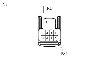
1.CHECK HARNESS AND CONNECTOR (AIR CONDITIONING CONTROL ASSEMBLY - POWER SOURCE)
a.
E281478C01
1.51,0.208 1.906,0.458 0.396,0.25 1.958,1.385 2.198,1.75 true 1.635,0.219 1.948,0.417 0.313,0.198 10 false F4 2.115,1.76 2.427,1.958 0.313,0.198 10 false IG+ 0.104,0.073 0.417,0.271 0.313,0.198 10 false *a
*a Front view of wire harness connector (to Air Conditioning Control Assembly)


Disconnect the air conditioning control assembly connector.


b.

Measure the voltage according to the value(s) in the table below.

Standard Voltage:
Tester Connection Switch Condition Specified Condition
F4-8 (IG+) - Body ground Ignition switch off Below 1 V
F4-8 (IG+) - Body ground Ignition switch ON 11 to 14 V


Result:
Proceed to
OK
NG


OK

2.CHECK HARNESS AND CONNECTOR (AIR CONDITIONING CONTROL ASSEMBLY - BODY GROUND)

NG

REPAIR OR REPLACE HARNESS OR CONNECTOR

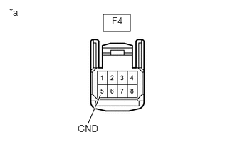
2.CHECK HARNESS AND CONNECTOR (AIR CONDITIONING CONTROL ASSEMBLY - BODY GROUND)
a.
E281478C02
1.51,0.208 1.906,0.458 0.396,0.25 1.469,1.385 1.292,1.792 true 1.635,0.219 1.948,0.417 0.313,0.198 10 false F4 1.135,1.792 1.448,1.99 0.313,0.198 10 false GND 0.135,0.094 0.448,0.292 0.313,0.198 10 false *a
*a Front view of wire harness connector (to Air Conditioning Control Assembly)


Disconnect the air conditioning control assembly connector.


b.

Measure the resistance according to the value(s) in the table below.

Standard Resistance:
Tester Connection Condition Specified Condition
F4-5 (GND) - Body ground Always Below 1 Ω


Result:
Proceed to
OK
NG


OK

3.CHECK HARNESS AND CONNECTOR (AIR CONDITIONING AMPLIFIER ASSEMBLY - AIR CONDITIONING CONTROL ASSEMBLY)

NG

REPAIR OR REPLACE HARNESS OR CONNECTOR

3.CHECK HARNESS AND CONNECTOR (AIR CONDITIONING AMPLIFIER ASSEMBLY - AIR CONDITIONING CONTROL ASSEMBLY)
a.

Disconnect the F3 air conditioning amplifier assembly connector.


b.

Disconnect the F4 air conditioning control assembly connector.


c.

Measure the resistance according to the value(s) in the table below.

Standard Resistance:
Tester Connection Condition Specified Condition
F3-4 (LIN1) - F4-2 (LIN1) Always Below 1 Ω
F3-4 (LIN1) or F4-2 (LIN1) - Body ground Always 10 kΩ or higher


Result:
Proceed to
OK
NG


OK

4.REPLACE AIR CONDITIONING CONTROL ASSEMBLY

NG

REPAIR OR REPLACE HARNESS OR CONNECTOR

4.REPLACE AIR CONDITIONING CONTROL ASSEMBLY
a.

Replace the air conditioning control assembly.

Click hereVehicle Interior>HEATING / AIR CONDITIONING>AIR CONDITIONING PANEL(for Automatic Air Conditioning System)>REMOVAL

HINT:

Since the air conditioning control assembly cannot be inspected while it is removed from the vehicle, replace the air conditioning control assembly with a new or known good one and check that the condition returns to normal.


OK:

Air conditioning control assembly operation returns to normal.


Result:
Result Proceed to
OK A
NG (When troubleshooting according to Problem Symptoms Table) B
NG (When troubleshooting according to the DTC) C


A

END (AIR CONDITIONING CONTROL ASSEMBLY WAS DEFECTIVE)

B

C

5.CHECK FOR DTC B1497
a.

Confirm whether of DTC B1497 is output.

Click hereVehicle Interior>HEATING / AIR CONDITIONING>AIR CONDITIONING SYSTEM(for Automatic Air Conditioning System)>DTC CHECK / CLEAR

NOTICE:

If the battery is disconnected, the past DTCs will be cleared.


Body Electrical > Air Conditioner > Trouble Codes
50001 121

Result:
Result Proceed to
DTC B1497 is not output A
DTC B1497 is output B


A

REPLACE AIR CONDITIONING AMPLIFIER ASSEMBLY

B

6.CHECK WHETHER DTC B1497 PROCEDURE HAS BEEN COMPLETED
a.

Check whether DTC B1497 procedure has been completed.


Result:
Result Proceed to
DTC B1497 check procedure has not been completed A
DTC B1497 check procedure has been completed B


A

B

REPLACE AIR CONDITIONING AMPLIFIER ASSEMBLY