POWER DISTRIBUTION MAIN BODY ECU REMOVAL
PROCEDURE

 55301
1.REMOVE INSTRUMENT PANEL SUB-ASSEMBLY
82817H
2.REMOVE WIRING HARNESS PROTECTOR
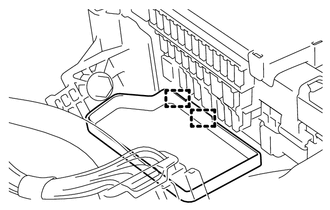
Disengage the 2 clamps to remove the wiring harness protector.
82730A
3.REMOVE DRIVER SIDE JUNCTION BLOCK ASSEMBLY
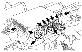
Disconnect the 8 connectors on the front side.
Remove the 2 bolts.
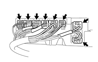
Disconnect the 8 connectors on the back side to remove the driver side junction block assembly.
89221B
4.REMOVE BODY COMPUTER
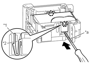
| *1 | Body Computer |
| *2 | Driver Side Junction Block Assembly |
| *a | Protective Tape |
Press in and hold the 2 tabs on the driver side junction block assembly side to disengage the 2 claws.
While pressing in the 2 tabs on the driver side junction block assembly side, insert a screwdriver with its tip wrapped in protective tape between the body computer and driver side junction block assembly.
- NOTICE:
-
Use a blade screwdriver with a diameter of 5.0 to 6.3 mm (0.197 to 0.248 in.), and with a length of 90 mm (3.543 in.) or more.
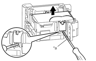
| *a | Protective Tape |
Do not pry the inserted screwdriver. Lift up the body computer to the point where the lock releases.
- NOTICE:
- ·
Do not twist the screwdriver to raise the body computer.
- ·
If any terminals of the connectors, locking parts or cases are deformed or damaged, replace the driver side junction block assembly or body computer.
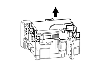
Disengage the 4 guides to remove the body computer by pulling it out from the driver side junction block assembly.