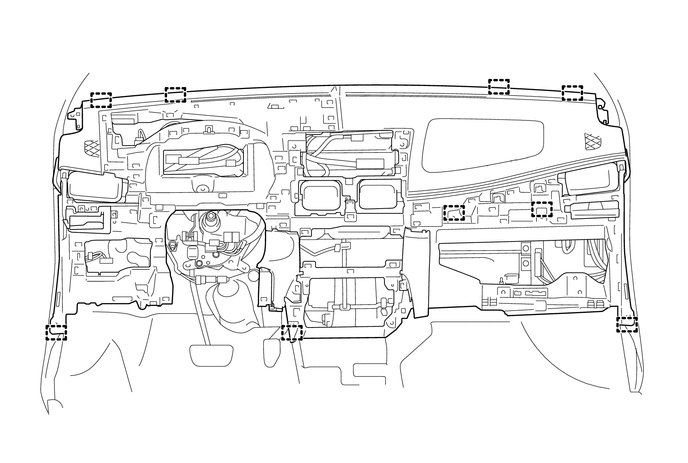
INTERIOR PANELS / TRIM INSTRUMENT PANEL SAFETY PAD REMOVAL
PROCEDURE

 1. PRECAUTION
Click hereVehicle Interior>INTERIOR PANELS / TRIM>INSTRUMENT PANEL SAFETY PAD>PRECAUTION
- NOTICE:
-
After turning the ignition switch off, waiting time may be required before disconnecting the cable from the negative (-) battery terminal. Therefore, make sure to read the disconnecting the cable from the negative (-) battery terminal notices before proceeding with work.
-
Click hereGeneral>INTRODUCTION>REPAIR INSTRUCTION>PRECAUTION
2.DISCONNECT CABLE FROM NEGATIVE BATTERY TERMINAL
- CAUTION:
-
Wait at least 90 seconds after disconnecting the cable from the negative (-) battery terminal to disable the SRS system.
62112
3.REMOVE COWL SIDE TRIM BOARD LH
62111C
4.REMOVE COWL SIDE TRIM BOARD RH
- HINT:
-
Use the same procedure as for the LH side.
62312B
5.DISCONNECT FRONT DOOR OPENING TRIM WEATHERSTRIP LH
Disconnect the front door opening trim weatherstrip LH.
62311B
6.DISCONNECT FRONT DOOR OPENING TRIM WEATHERSTRIP RH
- HINT:
-
Use the same procedure as for the LH side.
62212
7.REMOVE FRONT PILLAR GARNISH LH
62211
8.REMOVE FRONT PILLAR GARNISH RH
- HINT:
-
Use the same procedure as for the LH side.
55412D
9.REMOVE CENTER INSTRUMENT CLUSTER FINISH PANEL (w/ Radio Receiver)
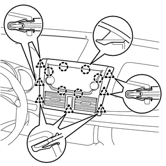
Disengage the 7 clips and the 6 claws.
Disconnect the connector and remove the center instrument cluster finish panel.
55412D
10.REMOVE CENTER INSTRUMENT CLUSTER FINISH PANEL (w/o Radio Receiver)
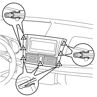
Disengage the 7 clips.
Disconnect the connector and remove the center instrument cluster finish panel.
11.REMOVE RADIO RECEIVER ASSEMBLY WITH BRACKET (w/ Radio Receiver)
12.REMOVE RADIO TUNER OPENING COVER WITH BRACKET (w/o Radio Receiver)
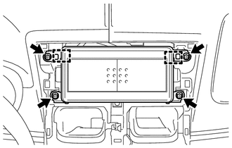
Remove the 4 screws.
Disengage the 2 guides and remove the radio tuner opening cover with bracket.
55606
13.REMOVE NO. 1 INSTRUMENT PANEL UNDER COVER SUB-ASSEMBLY
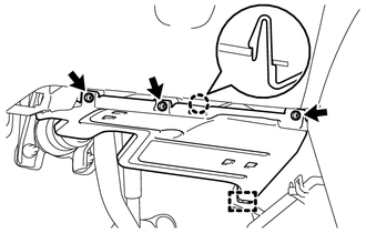
Remove the 3 screws <C>.
Disengage the claw and the guide and remove the No. 1 instrument panel under cover sub-assembly.
55432B
14.REMOVE LOWER INSTRUMENT PANEL FINISH PANEL (for LHD)
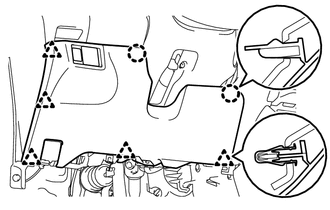
Disengage the 5 clips and the 2 claws.
Disconnect the connectors and remove the lower instrument panel finish panel.
55432B
15.REMOVE LOWER INSTRUMENT PANEL FINISH PANEL (for RHD)
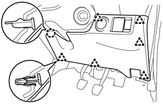
Disengage the 6 clips and the claw.
Disconnect the connectors and remove the lower instrument panel finish panel.
55411G
16.REMOVE NO. 1 INSTRUMENT CLUSTER FINISH PANEL
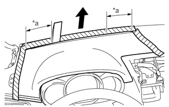
| *a | 170 mm (6.69 in) |

|
Protective Tape |
Apply protective tape as shown in the illustration.
Using a moulding remover, pry up on the No. 1 instrument cluster finish panel until there is enough of a gap to make it possible to pull on the panel by hand.
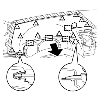
Pull the No. 1 instrument cluster finish panel in the direction indicated by the arrow to disengage the 12 clips and the 2 claws and the 4 guides and remove the No. 1 instrument cluster finish panel as shown in the illustration.
17.REMOVE UPPER CENTER INSTRUMENT CLUSTER FINISH PANEL
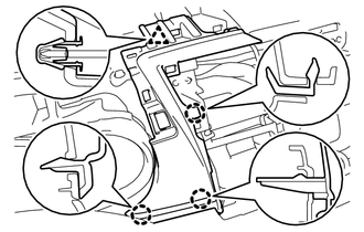
Disengage the 3 claws and the clip and remove the upper center instrument cluster finish panel.
84140
18.REMOVE HEADLIGHT DIMMER SWITCH ASSEMBLY
55474C
19.REMOVE NO. 1 INSTRUMENT CLUSTER FINISH PANEL GARNISH
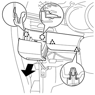
Pull the instrument panel cup holder sub-assembly in the direction indicated by the arrow.
Disengage the 2 claws and the 2 clips and remove the No. 1 instrument cluster finish panel garnish.
55650
20.REMOVE NO. 1 INSTRUMENT PANEL REGISTER ASSEMBLY (for LHD)
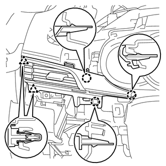
Disengage the 3 claws and the 2 clips and remove the No. 1 instrument panel register assembly.
55650
21.REMOVE NO. 1 INSTRUMENT PANEL REGISTER ASSEMBLY (for RHD)
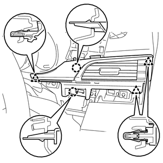
Disengage the 2 claws and the 3 clips and remove the No. 1 instrument panel register assembly.
55604A
22.REMOVE INSTRUMENT PANEL CUP HOLDER SUB-ASSEMBLY (for Driver Side)
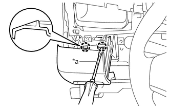
| *a | Protective Tape |
Using a screwdriver with its tip wrapped in protective tape, disengage the 2 claws and remove the instrument panel cup holder sub-assembly.
55410C
23.REMOVE INSTRUMENT CLUSTER FINISH PANEL ASSEMBLY
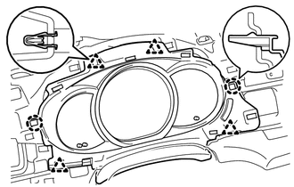
Disengage the 4 clips and the 2 claws and remove the instrument cluster finish panel assembly.
83100
24.REMOVE COMBINATION METER ASSEMBLY
55550
25.REMOVE GLOVE COMPARTMENT DOOR ASSEMBLY
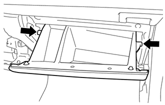
Slightly bend 2 stoppers in the directions indicated by the arrows in the illustration and pull the glove compartment door assembly until the stoppers are released.
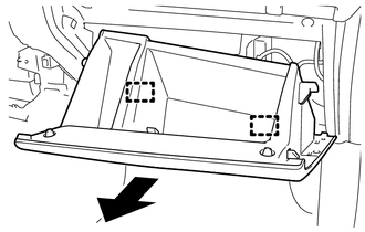
Open the glove compartment door assembly to approximately 47° from its closed position. Pull it horizontally in the direction indicated by the arrow to disengage the 2 hinges and remove the glove compartment door assembly.
- NOTICE:
- ·
Pulling the glove compartment door assembly upward to remove it causes the hinges to deform.
·Be sure to pull out the glove compartment door assembly horizontally.
55607
26.REMOVE NO. 2 INSTRUMENT PANEL UNDER COVER SUB-ASSEMBLY
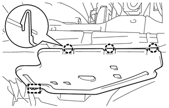
Disengage the 3 claws and the guide and remove the No. 2 instrument panel under cover sub-assembly.
55900
27.REMOVE AIR CONDITIONING CONTROL ASSEMBLY (for Automatic Air Conditioning System)
55902C
28.REMOVE AIR CONDITIONING PANEL SUB-ASSEMBLY (for Manual Air Conditioning System)
55900A
29.REMOVE HEATER CONTROL AND ACCESSORY ASSEMBLY (for Manual Air Conditioning System)
55604B
30.REMOVE INSTRUMENT PANEL CUP HOLDER SUB-ASSEMBLY (for Front Passenger Side)
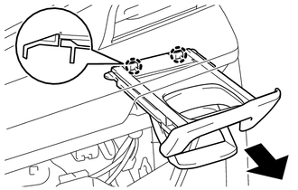
Pull the instrument panel cup holder sub-assembly in the direction indicated by the arrow.
Disengage the 2 claws and remove the instrument panel cup holder sub-assembly.
55475A
31.REMOVE NO. 2 INSTRUMENT CLUSTER FINISH PANEL GARNISH
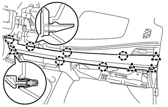
Disengage the 6 claws and the 4 clips and remove the No. 2 instrument cluster finish panel garnish.
55660
32.REMOVE NO. 2 INSTRUMENT PANEL REGISTER ASSEMBLY
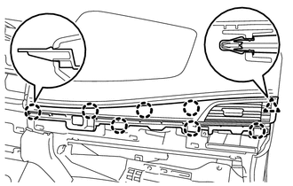
Disengage the 7 claws and the clip and remove the No. 2 instrument panel register assembly.
58910C
33.REMOVE REAR CONSOLE BOX ASSEMBLY
82142A
34.DISCONNECT INSTRUMENT PANEL WIRE (w/ Airbag System)
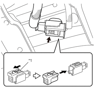
| *1 | Slider |
Slide the slider to release the lock, and then disconnect the connector.
- NOTICE:
-
When disconnecting any airbag connector, take care not to damage the airbag wire harness.
53601
35.DISCONNECT HOOD LOCK CONTROL LEVER SUB-ASSEMBLY
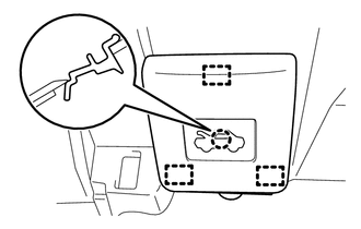
Disengage the claw and the 3 guides and disconnect the hood lock control lever sub-assembly.
55301
36.REMOVE INSTRUMENT PANEL SUB-ASSEMBLY
Disconnect the connectors.
Disengage the clamps.
for Automatic Air Conditioning System:
Disconnect the cooler thermistor hose.
Remove the 4 bolts <A>, 2 bolts <E>, bolt <D> and 2 screws <B>.
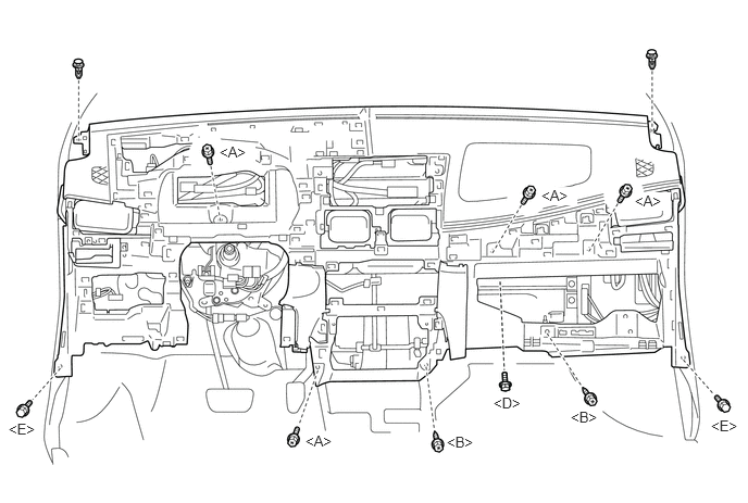
Remove the 2 clips.
Disengage the 9 guides and remove the instrument panel sub-assembly.