POWER ASSIST SYSTEMS POWER STEERING SYSTEM C1553 PIG Power Supply Overvoltage
DESCRIPTION
If the power steering ECU assembly determines that the motor power source voltage and IG voltage are not within the specified range, it stops the power assist as a fail-safe function.
| DTC No. | Detection Item | DTC Detection Condition | Trouble Area | Return-to-normal Condition | Note |
|---|---|---|---|---|---|
| C1553 | PIG Power Supply Overvoltage | Either condition is met:
·
PIG power source overvoltage. ·
IG power source overvoltage. |
·
EPS fuse ·
EPS-IG fuse ·
IG and PIG power source circuits ·
Power steering ECU assembly |
Ignition switch turned to ON again or after system confirmed to be normal | Power Steering Warning Light comes on. |
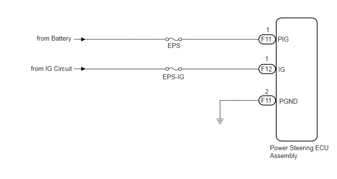
WIRING DIAGRAM
CAUTION / NOTICE / HINT
- NOTICE:
- ·
If the power steering ECU assembly, electric power steering column sub-assembly or power steering motor assembly have been replaced, perform torque sensor zero point calibration.
Click hereSteering>POWER ASSIST SYSTEMS>POWER STEERING SYSTEM>CALIBRATION
·Inspect the fuses for circuits related to this system before performing the following inspection procedure.
PROCEDURE
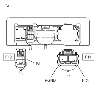
| *a | Rear view of wire harness connector
(to Power Steering ECU Assembly) |
Disconnect the power steering ECU assembly connectors.
Measure the voltage according to the value(s) in the table below.
- Standard Voltage:
Tester Connection Switch Condition Specified Condition F11-1 (PIG) - F11-2 (PGND) Always 11 to 14 V F12-1 (IG) - F11-2 (PGND) Ignition switch ON 11 to 14 V
- Result:
Proceed to OK NG
OK
NG