CLUTCH CLUTCH PEDAL(for LHD) INSTALLATION
PROCEDURE

 31321
1.INSTALL CLUTCH PEDAL PAD
Install the clutch pedal pad to the clutch pedal sub-assembly.
31301C
2.INSTALL CLUTCH PEDAL BUSH
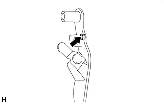
Install a new clutch pedal bush to the clutch pedal sub-assembly.
- HINT:
-
Install the clutch pedal bush from the right side of the vehicle.

|
MP Grease |
Apply MP grease to the inside of the clutch pedal bush.
31301B
3.INSTALL NO. 1 CLUTCH PEDAL CUSHION
Install the 2 No. 1 clutch pedal cushions to the clutch pedal sub-assembly.
31324A
4.INSTALL CLUTCH PEDAL SHAFT COLLAR
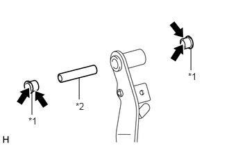
| *1 | Clutch Pedal Spring Bush |
| *2 | Clutch Pedal Shaft Collar |
|
|
MP Grease |
Apply MP grease to both sides of 2 new clutch pedal spring bushes.
Install the clutch pedal shaft collar and 2 clutch pedal spring bushes to the clutch pedal sub-assembly.
31301
5.INSTALL CLUTCH PEDAL SUB-ASSEMBLY
Install the clutch pedal sub-assembly to the clutch pedal support sub-assembly with the bolt and nut.
- Torque:
- 36.8 N*m (375 kgf*cm, 27 ft.*lbf)
- HINT:
- ·
Install the bolt from the right side of the vehicle.
·Turn the nut while holding the bolt.
31301F
6.INSTALL CLUTCH PEDAL STOPPER BOLT
Install the clutch pedal stopper bolt to the clutch pedal support sub-assembly and temporarily tighten the lock nut.
- HINT:
-
Tighten the lock nut to the specified torque when adjusting the clutch pedal.
84520
7.INSTALL CLUTCH START SWITCH ASSEMBLY
Install the clutch start switch assembly to the clutch pedal support sub-assembly with the nut.
- Torque:
- 15.7 N*m (160 kgf*cm, 12 ft.*lbf)
- NOTICE:
- ·
Insert the protrusion of the clutch start switch assembly into the hole in the clutch pedal support sub-assembly.
·To prevent damage to the clutch start switch assembly, make sure not to rotate it during installation.
55107A
8.INSTALL CLUTCH PEDAL SUPPORT SUB-ASSEMBLY
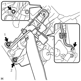
Temporarily install the clutch pedal support sub-assembly to the instrument panel reinforcement and clutch master cylinder assembly with the bolt and 2 nuts.
Tighten the bolt and 2 nuts in the order shown in the illustration.
- Torque:
- Nut : 9.0 N*m (92 kgf*cm, 80 in.*lbf)
- Bolt : 23.6 N*m (241 kgf*cm, 17 ft.*lbf)
Engage the clamp to the clutch pedal support sub-assembly.
Connect the connector to the clutch start switch assembly.
31453
9.CONNECT CLUTCH MASTER CYLINDER PUSH ROD CLEVIS
|
|
MP Grease |
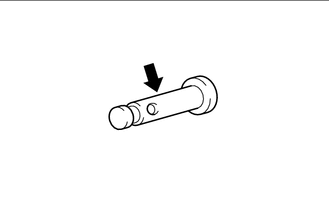
Apply MP grease to the push rod clevis pin.
Connect the clutch master cylinder push rod clevis to the clutch pedal sub-assembly with the push rod clevis pin.
- HINT:
-
Install the push rod clevis pin from the right side of the vehicle.
Install a new clip to the push rod clevis pin.
31301A
10.INSTALL CLUTCH PEDAL SPRING
Install the clutch pedal spring to the clutch pedal support sub-assembly and push rod clevis pin.
11.INSPECT AND ADJUST CLUTCH PEDAL
12.INSPECT CLUTCH START SYSTEM
55432B
13.INSTALL LOWER INSTRUMENT PANEL FINISH PANEL
55606
14.INSTALL NO. 1 INSTRUMENT PANEL UNDER COVER SUB-ASSEMBLY
55411G
15.INSTALL NO. 1 INSTRUMENT CLUSTER FINISH PANEL