1NR-FE INTAKE / EXHAUST INTAKE MANIFOLD INSTALLATION
PROCEDURE

 1.INSTALL GROMMET
Install the grommet to the intake manifold.
17111
2.INSTALL INTAKE MANIFOLD (for CVT)
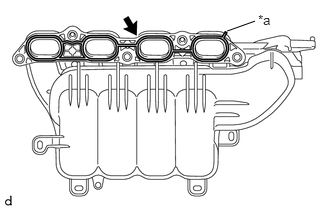
| *a | Protrusion of No. 1 Intake Manifold to Head Gasket |
Install a new No. 1 intake manifold to head gasket to the intake manifold.
- HINT:
-
When installing the No. 1 intake manifold to head gasket, align the protrusion of the intake manifold to head gasket with the groove of the intake manifold.
Temporarily install the intake manifold to the cylinder head sub-assembly with the 3 bolts and 2 nuts.
- NOTICE:
-
Make sure there is no oil adhering to the bolts or threaded holes.
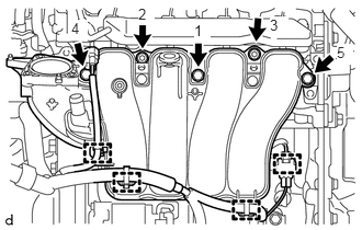
Tighten the 3 bolts and 2 nuts in the order shown in the illustration.
- Torque:
- 28 N*m (286 kgf*cm, 21 ft.*lbf)
Engage the 4 clamps to connect the wire harness to the intake manifold.
Engage the clamp to connect the No. 1 air hose to the intake manifold.
Install the vacuum switching valve assembly to the intake manifold with the bolt.
- Torque:
- 12 N*m (122 kgf*cm, 9 ft.*lbf)
17111
3.INSTALL INTAKE MANIFOLD (for Manual Transaxle)
| *a | Protrusion of No. 1 Intake Manifold to Head Gasket |
Install a new No. 1 intake manifold to head gasket to the intake manifold.
- HINT:
-
When installing the No. 1 intake manifold to head gasket, align the protrusion of the intake manifold to head gasket with the groove of the intake manifold.
Temporarily install the intake manifold to the cylinder head sub-assembly with the 3 bolts and 2 nuts.
- NOTICE:
-
Make sure there is no oil adhering to the bolts or threaded holes.
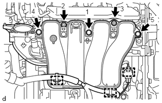
Tighten the 3 bolts and 2 nuts in the order shown in the illustration.
- Torque:
- 28 N*m (286 kgf*cm, 21 ft.*lbf)
Engage the 3 clamps to connect the wire harness to the intake manifold.
12261
4.CONNECT VENTILATION HOSE
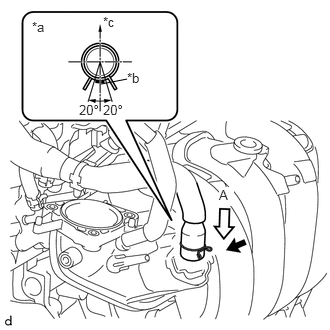
| *a | View A |
| *b | Paint Mark |
| *c | Exhaust Side |
Connect the ventilation hose to the intake manifold and slide the hose clip to secure it.
- NOTICE:
-
Perform the installation with the ventilation hose and hose clip at the correct angle.
23827A
5.CONNECT NO. 2 FUEL VAPOR FEED HOSE
Connect the No. 2 fuel vapor feed hose to the intake manifold.
44774
6.CONNECT UNION TO CONNECTOR TUBE HOSE (for CVT)
44774
7.CONNECT UNION TO CONNECTOR TUBE HOSE (for Manual Transaxle)
22030
8.INSTALL THROTTLE BODY WITH MOTOR ASSEMBLY
55781E
9.INSTALL COWL TOP VENTILATOR LOUVER SUB-ASSEMBLY
10.INSPECT INTAKE SYSTEM