1NR-FE ENGINE CONTROL THROTTLE BODY INSTALLATION
PROCEDURE

 22271
1.INSTALL THROTTLE BODY GASKET
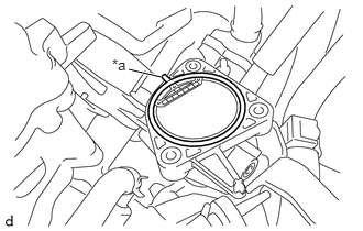
| *a | Protrusion of Throttle Body Gasket |
Install a new throttle body gasket to the intake manifold
- NOTICE:
-
Check that the gasket is securely fitted into the groove on the intake manifold.
22030
2.INSTALL THROTTLE BODY WITH MOTOR ASSEMBLY
Install the throttle body with motor assembly and wire harness clamp bracket to the intake manifold with the 3 bolts.
- Torque:
- 10 N*m (102 kgf*cm, 7 ft.*lbf)
- NOTICE:
-
If a component has been dropped or subjected to a strong impact, replace the throttle body with motor assembly.
- HINT:
-
Perform "Inspection After Repairs" after replacing the throttle body with motor assembly.
-
Click hereEngine / Hybrid System>1NR-FE ENGINE CONTROL>SFI SYSTEM>INITIALIZATION
16264
3.CONNECT NO. 2 WATER BY-PASS HOSE
Connect the No. 2 water by-pass hose to the throttle body with motor assembly and slide the hose clip to secure it.
16267
4.CONNECT NO. 3 WATER BY-PASS HOSE
Connect the No. 3 water by-pass hose to the throttle body with motor assembly and slide the hose clip to secure it.
12261
5.CONNECT VENTILATION HOSE
Connect the ventilation hose to the PCV valve (ventilation valve sub-assembly) and slide the hose clip to secure it.
Engage the 2 clamps to connect the ventilation hose to the 2 hose clamps.
6.INSTALL WIRE HARNESS CLAMP BRACKET
Install the wire harness clamp bracket to the intake manifold and wire harness clamp bracket with the 2 bolts.
- Torque:
- 8.4 N*m (86 kgf*cm, 74 in.*lbf)
Engage the clamp to connect the hose clamp to the wire harness clamp bracket.
Connect the throttle body with motor assembly connector.
Engage the clamp to connect the wire harness to the wire harness clamp bracket.
7.INSTALL AIR CLEANER HOSE ASSEMBLY
Connect the air cleaner hose assembly to the throttle body with motor assembly and unlock the hose clip to secure it.
Connect the air cleaner hose assembly to the air cleaner cap sub-assembly and tighten the hose clamp.
- Torque:
- 3.0 N*m (31 kgf*cm, 27 in.*lbf)
Engage the clamp to connect the purge VSV to the air cleaner hose assembly.
12262
8.CONNECT NO. 2 VENTILATION HOSE
Connect the No. 2 ventilation hose to the air cleaner hose assembly and slide the hose clip to secure it.
17341T
9.CONNECT NO. 1 AIR HOSE (for CVT)
Connect the No. 1 air hose to the air cleaner hose assembly and slide the hose clip to secure it.
10.ADD ENGINE COOLANT
11.INSPECT FOR ENGINE COOLANT LEAK
12611
12.INSTALL NO. 1 ENGINE COVER
13.PERFORM INITIALIZATION
- NOTICE:
-
Perform the following procedure after replacing the throttle body with motor assembly or any throttle body with motor assembly components. The following procedure should also be performed if the throttle body with motor assembly is cleaned.
Disconnect the cable from the negative (-) battery terminal. Wait at least 60 seconds and reconnect the cable.
Turn the ignition switch to ON without operating the accelerator pedal.
- NOTICE:
-
If the accelerator pedal is operated, perform the above step again.
Connect the GTS to the DLC3.
Clear the DTCs.
Click hereEngine / Hybrid System>1NR-FE ENGINE CONTROL>SFI SYSTEM>DTC CHECK / CLEAR
Perform "Inspection After Repairs".
Click hereEngine / Hybrid System>1NR-FE ENGINE CONTROL>SFI SYSTEM>INITIALIZATION
Start the engine and check that the MIL is not illuminated. After the engine is warmed up, check that the idle speed is within the specified range with the A/C switch off (w/ air conditioning system).
- Standard idle speed:
Transaxle Idle Speed Continuously Variable Transaxle 600 to 700 rpm Manual Transaxle 550 to 650 rpm
- NOTICE:
- ·
Turn all electrical systems and the A/C off (w/ air conditioning system).
·Inspect the idle speed with the cooling fans off.
·When checking the idle speed, the transaxle should be in neutral or park
Enter the following menus: Powertrain / Engine and ECT / Data List / Throttle Sensor Position.
- Powertrain > Engine and ECT > Data List
-
Tester Display Throttle Sensor Position - 50003 234 12
Fully depress the accelerator pedal and check that the value of Throttle Sensor Position is 60% or higher.
Perform a road test and confirm that there are no abnormalities.